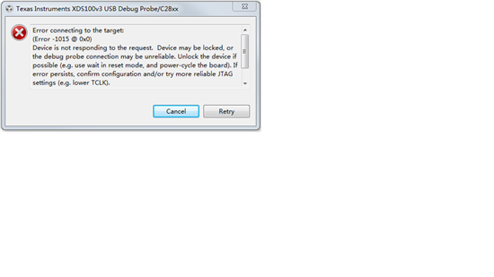
做了几块板子,其中有一块自从第二次烧程序开始就一直失败,提示如下,想问该怎么办,CCS的设置应该都没问题,因为其他板子可以烧写。
在CCS里的ccxml中点击了test connection功能,返回结果是:
[Start: Texas Instruments XDS100v3 USB Debug Probe]
Execute the command:
%ccs_base%/common/uscif/dbgjtag -f %boarddatafile% -rv -o -F inform,logfile=yes -S pathlength -S integrity
[Result]
—–[Print the board config pathname(s)]————————————
C:\Users\xiatian\AppData\Local\TEXASI~1\
CCS\ti\0\0\BrdDat\testBoard.dat
—–[Print the reset-command software log-file]—————————–
This utility has selected a 100- or 510-class product.
This utility will load the adapter 'jioserdesusbv3.dll'.
The library build date was 'Feb 18 2015'.
The library build time was '23:56:50'.
The library package version is '5.1.641.0'.
The library component version is '35.34.40.0'.
The controller does not use a programmable FPGA.
The controller has a version number of '4' (0x00000004).
The controller has an insertion length of '0' (0x00000000).
This utility will attempt to reset the controller.
This utility has successfully reset the controller.
—–[Print the reset-command hardware log-file]—————————–
The scan-path will be reset by toggling the JTAG TRST signal.
The controller is the FTDI FT2232 with USB interface.
The link from controller to target is direct (without cable).
The software is configured for FTDI FT2232 features.
The controller cannot monitor the value on the EMU[0] pin.
The controller cannot monitor the value on the EMU[1] pin.
The controller cannot control the timing on output pins.
The controller cannot control the timing on input pins.
The scan-path link-delay has been set to exactly '0' (0x0000).
—–[The log-file for the JTAG TCLK output generated from the PLL]———-
Test Size Coord MHz Flag Result Description
~~~~ ~~~~ ~~~~~~~ ~~~~~~~~ ~~~~ ~~~~~~~~~~~ ~~~~~~~~~~~~~~~~~~~
1 512 – 01 00 500.0kHz O good value measure path length
2 512 + 00 00 1.000MHz [O] good value apply explicit tclk
There is no hardware for measuring the JTAG TCLK frequency.
In the scan-path tests:
The test length was 16384 bits.
The JTAG IR length was 38 bits.
The JTAG DR length was 1 bits.
The IR/DR scan-path tests used 2 frequencies.
The IR/DR scan-path tests used 500.0kHz as the initial frequency.
The IR/DR scan-path tests used 1.000MHz as the highest frequency.
The IR/DR scan-path tests used 1.000MHz as the final frequency.
—–[Measure the source and frequency of the final JTAG TCLKR input]——–
There is no hardware for measuring the JTAG TCLK frequency.
—–[Perform the standard path-length test on the JTAG IR and DR]———–
This path-length test uses blocks of 512 32-bit words.
The test for the JTAG IR instruction path-length succeeded.
The JTAG IR instruction path-length is 38 bits.
The test for the JTAG DR bypass path-length succeeded.
The JTAG DR bypass path-length is 1 bits.
—–[Perform the Integrity scan-test on the JTAG IR]————————
This test will use blocks of 512 32-bit words.
This test will be applied just once.
Do a test using 0xFFFFFFFF.
Scan tests: 1, skipped: 0, failed: 0
Do a test using 0x00000000.
Scan tests: 2, skipped: 0, failed: 0
Do a test using 0xFE03E0E2.
Scan tests: 3, skipped: 0, failed: 0
Do a test using 0x01FC1F1D.
Scan tests: 4, skipped: 0, failed: 0
Do a test using 0x5533CCAA.
Scan tests: 5, skipped: 0, failed: 0
Do a test using 0xAACC3355.
Scan tests: 6, skipped: 0, failed: 0
All of the values were scanned correctly.
The JTAG IR Integrity scan-test has succeeded.
—–[Perform the Integrity scan-test on the JTAG DR]————————
This test will use blocks of 512 32-bit words.
This test will be applied just once.
Do a test using 0xFFFFFFFF.
Scan tests: 1, skipped: 0, failed: 0
Do a test using 0x00000000.
Scan tests: 2, skipped: 0, failed: 0
Do a test using 0xFE03E0E2.
Scan tests: 3, skipped: 0, failed: 0
Do a test using 0x01FC1F1D.
Scan tests: 4, skipped: 0, failed: 0
Do a test using 0x5533CCAA.
Scan tests: 5, skipped: 0, failed: 0
Do a test using 0xAACC3355.
Scan tests: 6, skipped: 0, failed: 0
All of the values were scanned correctly.
The JTAG DR Integrity scan-test has succeeded.
[End: Texas Instruments XDS100v3 USB Debug Probe]
谢谢!
rookiecalf:
感觉还是焊接质量有问题
做了几块板子,其中有一块自从第二次烧程序开始就一直失败,提示如下,想问该怎么办,CCS的设置应该都没问题,因为其他板子可以烧写。
在CCS里的ccxml中点击了test connection功能,返回结果是:
[Start: Texas Instruments XDS100v3 USB Debug Probe]
Execute the command:
%ccs_base%/common/uscif/dbgjtag -f %boarddatafile% -rv -o -F inform,logfile=yes -S pathlength -S integrity
[Result]
—–[Print the board config pathname(s)]————————————
C:\Users\xiatian\AppData\Local\TEXASI~1\
CCS\ti\0\0\BrdDat\testBoard.dat
—–[Print the reset-command software log-file]—————————–
This utility has selected a 100- or 510-class product.
This utility will load the adapter 'jioserdesusbv3.dll'.
The library build date was 'Feb 18 2015'.
The library build time was '23:56:50'.
The library package version is '5.1.641.0'.
The library component version is '35.34.40.0'.
The controller does not use a programmable FPGA.
The controller has a version number of '4' (0x00000004).
The controller has an insertion length of '0' (0x00000000).
This utility will attempt to reset the controller.
This utility has successfully reset the controller.
—–[Print the reset-command hardware log-file]—————————–
The scan-path will be reset by toggling the JTAG TRST signal.
The controller is the FTDI FT2232 with USB interface.
The link from controller to target is direct (without cable).
The software is configured for FTDI FT2232 features.
The controller cannot monitor the value on the EMU[0] pin.
The controller cannot monitor the value on the EMU[1] pin.
The controller cannot control the timing on output pins.
The controller cannot control the timing on input pins.
The scan-path link-delay has been set to exactly '0' (0x0000).
—–[The log-file for the JTAG TCLK output generated from the PLL]———-
Test Size Coord MHz Flag Result Description
~~~~ ~~~~ ~~~~~~~ ~~~~~~~~ ~~~~ ~~~~~~~~~~~ ~~~~~~~~~~~~~~~~~~~
1 512 – 01 00 500.0kHz O good value measure path length
2 512 + 00 00 1.000MHz [O] good value apply explicit tclk
There is no hardware for measuring the JTAG TCLK frequency.
In the scan-path tests:
The test length was 16384 bits.
The JTAG IR length was 38 bits.
The JTAG DR length was 1 bits.
The IR/DR scan-path tests used 2 frequencies.
The IR/DR scan-path tests used 500.0kHz as the initial frequency.
The IR/DR scan-path tests used 1.000MHz as the highest frequency.
The IR/DR scan-path tests used 1.000MHz as the final frequency.
—–[Measure the source and frequency of the final JTAG TCLKR input]——–
There is no hardware for measuring the JTAG TCLK frequency.
—–[Perform the standard path-length test on the JTAG IR and DR]———–
This path-length test uses blocks of 512 32-bit words.
The test for the JTAG IR instruction path-length succeeded.
The JTAG IR instruction path-length is 38 bits.
The test for the JTAG DR bypass path-length succeeded.
The JTAG DR bypass path-length is 1 bits.
—–[Perform the Integrity scan-test on the JTAG IR]————————
This test will use blocks of 512 32-bit words.
This test will be applied just once.
Do a test using 0xFFFFFFFF.
Scan tests: 1, skipped: 0, failed: 0
Do a test using 0x00000000.
Scan tests: 2, skipped: 0, failed: 0
Do a test using 0xFE03E0E2.
Scan tests: 3, skipped: 0, failed: 0
Do a test using 0x01FC1F1D.
Scan tests: 4, skipped: 0, failed: 0
Do a test using 0x5533CCAA.
Scan tests: 5, skipped: 0, failed: 0
Do a test using 0xAACC3355.
Scan tests: 6, skipped: 0, failed: 0
All of the values were scanned correctly.
The JTAG IR Integrity scan-test has succeeded.
—–[Perform the Integrity scan-test on the JTAG DR]————————
This test will use blocks of 512 32-bit words.
This test will be applied just once.
Do a test using 0xFFFFFFFF.
Scan tests: 1, skipped: 0, failed: 0
Do a test using 0x00000000.
Scan tests: 2, skipped: 0, failed: 0
Do a test using 0xFE03E0E2.
Scan tests: 3, skipped: 0, failed: 0
Do a test using 0x01FC1F1D.
Scan tests: 4, skipped: 0, failed: 0
Do a test using 0x5533CCAA.
Scan tests: 5, skipped: 0, failed: 0
Do a test using 0xAACC3355.
Scan tests: 6, skipped: 0, failed: 0
All of the values were scanned correctly.
The JTAG DR Integrity scan-test has succeeded.
[End: Texas Instruments XDS100v3 USB Debug Probe]
谢谢!
XiaTian:
回复 rookiecalf:
但是test connection结果显示通过了测试了。
我在网上查到UNIFLASH可以用来解锁,但安装了3.3版本以后只是在开始菜单里多了个UNIFLASH的文档


