S1开关已经拨到111位置,板子自身演示程序可以运行。提示如下: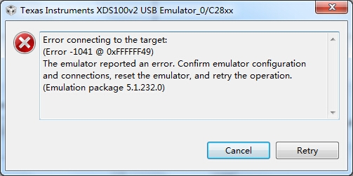
连接测试如下:
[Start]
Execute the command:
%ccs_base%/common/uscif/dbgjtag -f %boarddatafile% -rv -o -F inform,logfile=yes -S pathlength -S integrity
[Result]
—–[Print the board config pathname(s)]————————————
C:\Users\michael\AppData\Local\.TI\499279040\
0\0\BrdDat\testBoard.dat
—–[Print the reset-command software log-file]—————————–
This utility has selected a 100- or 510-class product.
This utility will load the adapter 'jioserdesusb.dll'.
The library build date was 'Aug 20 2013'.
The library build time was '22:56:19'.
The library package version is '5.1.232.0'.
The library component version is '35.34.40.0'.
The controller does not use a programmable FPGA.
The controller has a version number of '4' (0x00000004).
The controller has an insertion length of '0' (0x00000000).
This utility will attempt to reset the controller.
This utility has successfully reset the controller.
—–[Print the reset-command hardware log-file]—————————–
The scan-path will be reset by toggling the JTAG TRST signal.
The controller is the FTDI FT2232 with USB interface.
The link from controller to target is direct (without cable).
The software is configured for FTDI FT2232 features.
The controller cannot monitor the value on the EMU[0] pin.
The controller cannot monitor the value on the EMU[1] pin.
The controller cannot control the timing on output pins.
The controller cannot control the timing on input pins.
The scan-path link-delay has been set to exactly '0' (0x0000).
—–[The log-file for the JTAG TCLK output generated from the PLL]———-
There is no hardware for programming the JTAG TCLK frequency.
—–[Measure the source and frequency of the final JTAG TCLKR input]——–
There is no hardware for measuring the JTAG TCLK frequency.
—–[Perform the standard path-length test on the JTAG IR and DR]———–
This path-length test uses blocks of 512 32-bit words.
The JTAG IR instruction path-length was not recorded.
—–[Perform the Integrity scan-test on the JTAG IR]————————
This test will use blocks of 512 32-bit words.
This test will be applied just once.
Do a test using 0xFFFFFFFF.
Scan tests: 1, skipped: 0, failed: 0
—–[An error has occurred and this utility has aborted]——————–
This error is generated by TI's USCIF driver or utilities.
The value is '-183' (0xffffff49).
The title is 'SC_ERR_CTL_CBL_BREAK_FAR'.
The explanation is:
The controller has detected a cable break far-from itself.
The user must connect the cable/pod to the target.
[End]
请问怎么解决?
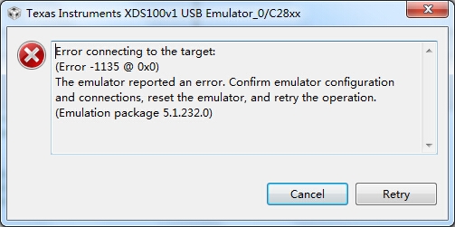
yuan michael:
把target configuration里把xds100v2 改成 XDSV100V1测试倒是通过了,但是还是连接不上,如下图:
[Start]
Execute the command:
%ccs_base%/common/uscif/dbgjtag -f %boarddatafile% -rv -o -F inform,logfile=yes -S pathlength -S integrity
[Result]
—–[Print the board config pathname(s)]————————————
C:\Users\michael\AppData\Local\.TI\499279040\ 0\0\BrdDat\testBoard.dat
—–[Print the reset-command software log-file]—————————–
This utility has selected a 100- or 510-class product.This utility will load the adapter 'jioserdesusb.dll'.The library build date was 'Aug 20 2013'.The library build time was '22:56:19'.The library package version is '5.1.232.0'.The library component version is '35.34.40.0'.The controller does not use a programmable FPGA.The controller has a version number of '4' (0x00000004).The controller has an insertion length of '0' (0x00000000).This utility will attempt to reset the controller.This utility has successfully reset the controller.
—–[Print the reset-command hardware log-file]—————————–
The scan-path will be reset by toggling the JTAG TRST signal.The controller is the FTDI FT2232 with USB interface.The link from controller to target is direct (without cable).The software is configured for FTDI FT2232 features.The controller cannot monitor the value on the EMU[0] pin.The controller cannot monitor the value on the EMU[1] pin.The controller cannot control the timing on output pins.The controller cannot control the timing on input pins.The scan-path link-delay has been set to exactly '0' (0x0000).
—–[The log-file for the JTAG TCLK output generated from the PLL]———-
There is no hardware for programming the JTAG TCLK frequency.
—–[Measure the source and frequency of the final JTAG TCLKR input]——–
There is no hardware for measuring the JTAG TCLK frequency.
—–[Perform the standard path-length test on the JTAG IR and DR]———–
This path-length test uses blocks of 512 32-bit words.
The test for the JTAG IR instruction path-length succeeded.The JTAG IR instruction path-length is 0 bits.
The test for the JTAG DR bypass path-length succeeded.The JTAG DR bypass path-length is 0 bits.
—–[Perform the Integrity scan-test on the JTAG IR]————————
This test will use blocks of 512 32-bit words.This test will be applied just once.
Do a test using 0xFFFFFFFF.Scan tests: 1, skipped: 0, failed: 0Do a test using 0x00000000.Scan tests: 2, skipped: 0, failed: 0Do a test using 0xFE03E0E2.Scan tests: 3, skipped: 0, failed: 0Do a test using 0x01FC1F1D.Scan tests: 4, skipped: 0, failed: 0Do a test using 0x5533CCAA.Scan tests: 5, skipped: 0, failed: 0Do a test using 0xAACC3355.Scan tests: 6, skipped: 0, failed: 0All of the values were scanned correctly.
The JTAG IR Integrity scan-test has succeeded.
—–[Perform the Integrity scan-test on the JTAG DR]————————
This test will use blocks of 512 32-bit words.This test will be applied just once.
Do a test using 0xFFFFFFFF.Scan tests: 1, skipped: 0, failed: 0Do a test using 0x00000000.Scan tests: 2, skipped: 0, failed: 0Do a test using 0xFE03E0E2.Scan tests: 3, skipped: 0, failed: 0Do a test using 0x01FC1F1D.Scan tests: 4, skipped: 0, failed: 0Do a test using 0x5533CCAA.Scan tests: 5, skipped: 0, failed: 0Do a test using 0xAACC3355.Scan tests: 6, skipped: 0, failed: 0All of the values were scanned correctly.
The JTAG DR Integrity scan-test has succeeded.
[End]
大家有遇到这种情况,或者有什么建议吗?谢谢!


