使用f28335
我們自己用了一個版子
僅拉出 部分接腳 和電源供給
目標是
斷電後程是能重跑
不會因為ccs的resume鍵停止 而停止
希望不用透過resume就可以自動執行
Green Deng:你好,芯片运行分为在线调试的时候RAM运行和离线情况下的FLASH运行。只要正确添加flash烧写用的cmd文件就可以使芯片在脱离CCS后运行了
使用f28335
我們自己用了一個版子
僅拉出 部分接腳 和電源供給
目標是
斷電後程是能重跑
不會因為ccs的resume鍵停止 而停止
希望不用透過resume就可以自動執行
user5913644:
回复 Green Deng:
要怎麼寫進flash 已經有cmd檔了 不知道怎麼燒進去
使用f28335
我們自己用了一個版子
僅拉出 部分接腳 和電源供給
目標是
斷電後程是能重跑
不會因為ccs的resume鍵停止 而停止
希望不用透過resume就可以自動執行
Green Deng:
回复 user5913644:
注意图片中的3个红色位置:
1、工程中已经添加cmd文件(同时要右键ram运行的cmd文件选择exclude from build,确保工程只包含一个cmd文件)。2、工程属性的include中已经包含cmd文件的路径。
如果以上两项已经满足,那么编译后再debug的话,程序就会烧写进flash中运行,同时可以掉电不删除。
使用f28335
我們自己用了一個版子
僅拉出 部分接腳 和電源供給
目標是
斷電後程是能重跑
不會因為ccs的resume鍵停止 而停止
希望不用透過resume就可以自動執行
user5913644:
回复 Green Deng:
圖片 我把sensorless .cmd和 nonBIOS.cmd右鍵exclude from build
但沒有在includes中看到cmd
使用f28335
我們自己用了一個版子
僅拉出 部分接腳 和電源供給
目標是
斷電後程是能重跑
不會因為ccs的resume鍵停止 而停止
希望不用透過resume就可以自動執行
user5913644:
回复 Green Deng:
使用F28335 如何使用FLASH
使用f28335
我們自己用了一個版子
僅拉出 部分接腳 和電源供給
目標是
斷電後程是能重跑
不會因為ccs的resume鍵停止 而停止
希望不用透過resume就可以自動執行
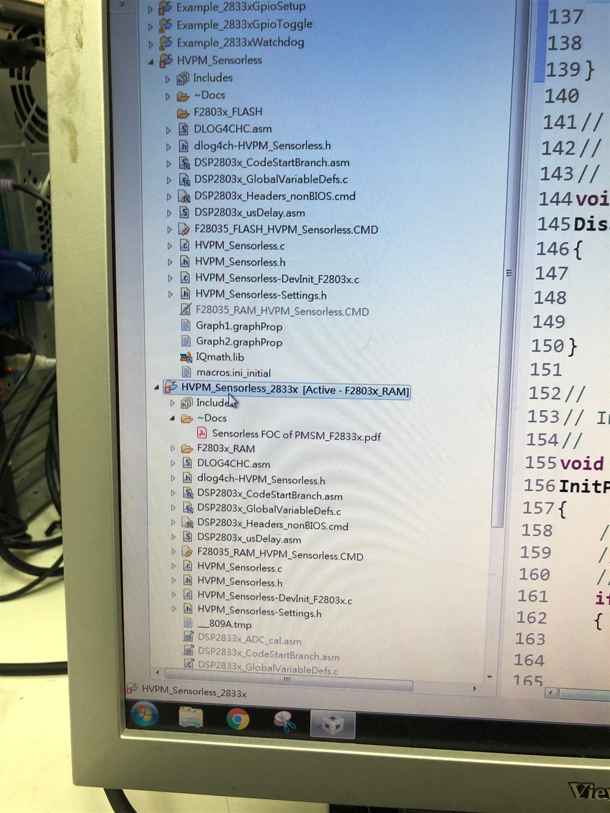
Green Deng:
回复 user5913644:
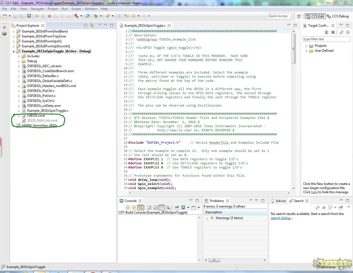
针对这个工程的话,注意截图上绿色圈出来的这几个文件。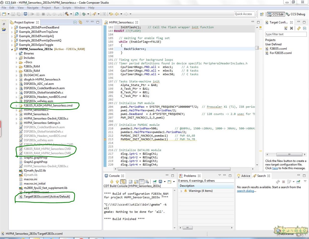
首先最下方的圈,要选择F28335芯片(最好点开确认一下)
其次另外两个圈出来的文件要互相替换掉,包含“…RAM…”的cmd文件右键选择exclude from build,将“…FLASH…”右键include from build去掉勾。
然后编译没问题就可以debug烧写进flash了。
操作这几个文件就可以了,其他文件不用动。
使用f28335
我們自己用了一個版子
僅拉出 部分接腳 和電源供給
目標是
斷電後程是能重跑
不會因為ccs的resume鍵停止 而停止
希望不用透過resume就可以自動執行
user5913644:
回复 Green Deng:
要怎麼調整 ram 到 flash
使用f28335
我們自己用了一個版子
僅拉出 部分接腳 和電源供給
目標是
斷電後程是能重跑
不會因為ccs的resume鍵停止 而停止
希望不用透過resume就可以自動執行
user5913644:
回复 user5913644:
/* ==============================================================================
System Name:HVPM_Sensorless
File Name:HVPM_Sensorless.C
Description: Primary system file for the Real Implementation of SensorlessField Orientation Control for Three Phase Permanent-MagnetSynchronous Motor (PMSM) Supports F2833x(floating point) and F2803x(fixed point) devices
=================================================================================*/
// Include header files used in the main function
#include "PeripheralHeaderIncludes.h"
#include "HVPM_Sensorless-Settings.h"
#include "IQmathLib.h"
#include "HVPM_Sensorless.h"
#include <math.h>
#ifdef FLASH
#pragma CODE_SECTION(MainISR,"ramfuncs");
#pragma CODE_SECTION(OffsetISR,"ramfuncs");
#endif
// Prototype statements for functions found within this file.
interrupt void MainISR(void);
interrupt void OffsetISR(void);
void DeviceInit();
void MemCopy();
void InitFlash();
void HVDMC_Protection(void);
// State Machine function prototypes
//————————————
// Alpha states
void A0(void); //state A0
void B0(void); //state B0
void C0(void); //state C0
// A branch states
void A1(void); //state A1
void A2(void); //state A2
void A3(void); //state A3
// B branch states
void B1(void); //state B1
void B2(void); //state B2
void B3(void); //state B3
// C branch states
void C1(void); //state C1
void C2(void); //state C2
void C3(void); //state C3
// Variable declarations
void (*Alpha_State_Ptr)(void); // Base States pointer
void (*A_Task_Ptr)(void);// State pointer A branch
void (*B_Task_Ptr)(void);// State pointer B branch
void (*C_Task_Ptr)(void);// State pointer C branch
// Used for running BackGround in flash, and ISR in RAM
extern Uint16 *RamfuncsLoadStart, *RamfuncsLoadEnd, *RamfuncsRunStart;
int16 VTimer0[4];// Virtual Timers slaved off CPU Timer 0 (A events)
int16 VTimer1[4];// Virtual Timers slaved off CPU Timer 1 (B events)
int16 VTimer2[4];// Virtual Timers slaved off CPU Timer 2 (C events)
int16 SerialCommsTimer;
// Global variables used in this system
Uint16 OffsetFlag=0;
_iq offsetA=0;
_iq offsetB=0;
_iq offsetC=0;
_iq K1=_IQ(0.998);//Offset filter coefficient K1: 0.05/(T+0.05);
_iq K2=_IQ(0.001999); //Offset filter coefficient K2: T/(T+0.05);
extern _iq IQsinTable[];
extern _iq IQcosTable[];
_iq VdTesting = _IQ(0.0);// Vd reference (pu)
_iq VqTesting = _IQ(0.15);// Vq reference (pu)
_iq IdRef = _IQ(0.0);// Id reference (pu)
_iq IqRef = _IQ(0.1);// Iq reference (pu)
#if (BUILDLEVEL<LEVEL3)// Speed reference (pu)
_iqSpeedRef = _IQ(0.15);// For Open Loop tests
#else
_iqSpeedRef = _IQ(0.3);// For Closed Loop tests
#endif
float32 T = 0.001/ISR_FREQUENCY;// Samping period (sec), see parameter.h
Uint32 IsrTicker = 0;
Uint16 BackTicker = 0;
Uint16 lsw=0;
Uint16 TripFlagDMC=0;//PWM trip status
// Default ADC initialization
int ChSel[16]= {0,0,0,0,0,0,0,0,0,0,0,0,0,0,0,0};
int TrigSel[16] = {5,5,5,5,5,5,5,5,5,5,5,5,5,5,5,5};
int ACQPS[16]= {8,8,8,8,8,8,8,8,8,8,8,8,8,8,8,8};
int16 DlogCh1 = 0;
int16 DlogCh2 = 0;
int16 DlogCh3 = 0;
int16 DlogCh4 = 0;
volatile Uint16 EnableFlag = FALSE;
Uint16 LockRotorFlag = FALSE;
Uint16 SpeedLoopPrescaler = 10;// Speed loop prescaler
Uint16 SpeedLoopCount = 1;// Speed loop counter
// Instance a position estimator
SMOPOS smo1 = SMOPOS_DEFAULTS;
// Instance a sliding-mode position observer constant Module
SMOPOS_CONST smo1_const = SMOPOS_CONST_DEFAULTS;
// Instance a QEP interface driver
QEP qep1 = QEP_DEFAULTS;
// Instance a few transform objects
CLARKE clarke1 = CLARKE_DEFAULTS;
PARK park1 = PARK_DEFAULTS;
IPARK ipark1 = IPARK_DEFAULTS;
// Instance PI regulators to regulate the d and qaxis currents, and speed
PI_CONTROLLER pi_spd = PI_CONTROLLER_DEFAULTS;
PI_CONTROLLER pi_id= PI_CONTROLLER_DEFAULTS;
PI_CONTROLLER pi_iq= PI_CONTROLLER_DEFAULTS;
// Instance a PWM driver instance
PWMGEN pwm1 = PWMGEN_DEFAULTS;
// Instance a PWM DAC driver instance
PWMDAC pwmdac1 = PWMDAC_DEFAULTS;
// Instance a Space Vector PWM modulator. This modulator generates a, b and c
// phases based on the d and q stationery reference frame inputs
SVGEN svgen1 = SVGEN_DEFAULTS;
// Instance a ramp controller to smoothly ramp the frequency
RMPCNTL rc1 = RMPCNTL_DEFAULTS;
// Instance a ramp generator to simulate an Anglele
RAMPGEN rg1 = RAMPGEN_DEFAULTS;
// Instance a phase voltage calculation
PHASEVOLTAGE volt1 = PHASEVOLTAGE_DEFAULTS;
// Instance a speed calculator based on QEP
SPEED_MEAS_QEP speed1 = SPEED_MEAS_QEP_DEFAULTS;
// Instance a speed calculator based on sliding-mode position observer
SPEED_ESTIMATION speed3 = SPEED_ESTIMATION_DEFAULTS;
// Create an instance of DATALOG Module
DLOG_4CH dlog = DLOG_4CH_DEFAULTS;
void Gpio_setup2(void);
void main(void)
{DeviceInit(); // Device Life support & GPIOGpio_setup2();
// Only used if running from FLASH
// Note that the variable FLASH is defined by the compiler
#ifdef FLASH
// Copy time critical code and Flash setup code to RAM
// TheRamfuncsLoadStart, RamfuncsLoadEnd, and RamfuncsRunStart
// symbols are created by the linker. Refer to the linker files. MemCopy(&RamfuncsLoadStart, &RamfuncsLoadEnd, &RamfuncsRunStart);
// Call Flash Initialization to setup flash waitstates
// This function must reside in RAMInitFlash(); // Call the flash wrapper init function
#endif //(FLASH)
// Waiting for enable flag setwhile (EnableFlag==FALSE){if(GpioDataRegs.GPCDAT.bit.GPIO85==1){//12v openif(GpioDataRegs.GPCDAT.bit.GPIO84==1){//24v openEnableFlag=1;lsw=1;
}}
BackTicker++;}
// Timing sync for background loops
// Timer period definitions found in device specific PeripheralHeaderIncludes.hCpuTimer0Regs.PRD.all =mSec1;// A tasksCpuTimer1Regs.PRD.all =mSec5;// B tasksCpuTimer2Regs.PRD.all =mSec50; // C tasks
// Tasks State-machine initAlpha_State_Ptr = &A0;A_Task_Ptr = &A1;B_Task_Ptr = &B1;C_Task_Ptr = &C1;
// Initialize PWM modulepwm1.PeriodMax = SYSTEM_FREQUENCY*1000000*T/2;// Prescaler X1 (T1), ISR period = T x 1pwm1.HalfPerMax=pwm1.PeriodMax/2;pwm1.Deadband= 2.0*SYSTEM_FREQUENCY;// 120 counts -> 2.0 usec for TBCLK = SYSCLK/1PWM_INIT_MACRO(1,2,3,pwm1)
// Initialize PWMDAC modulepwmdac1.PeriodMax=500;// @60Mhz, 1500->20kHz, 1000-> 30kHz, 500->60kHzpwmdac1.HalfPerMax=pwmdac1.PeriodMax/2;PWMDAC_INIT_MACRO(6,pwmdac1)// PWM 6A,6BPWMDAC_INIT_MACRO(7,pwmdac1)// PWM 7A,7B
// Initialize DATALOG moduledlog.iptr1 = &DlogCh1;dlog.iptr2 = &DlogCh2;dlog.iptr3 = &DlogCh3;dlog.iptr4 = &DlogCh4;dlog.trig_value = 0x1;dlog.size = 0x00c8;dlog.prescalar = 5;dlog.init(&dlog);
// Initialize ADC for DMC Kit Rev 1.1ChSel[0]=1;// Dummy meas. avoid 1st sample issue Rev0 Picollo*/ChSel[1]=1;// ChSelect: ADC A1-> Phase A Current ChSel[2]=9;// ChSelect: ADC B1-> Phase B Current ChSel[3]=3;// ChSelect: ADC A3-> Phase C CurrentChSel[4]=15; // ChSelect: ADC B7-> Phase A VoltageChSel[5]=14; // ChSelect: ADC B6-> Phase B VoltageChSel[6]=12; // ChSelect: ADC B4-> Phase C VoltageChSel[7]=7;// ChSelect: ADC A7-> DC BusVoltage
// Initialize ADC moduleADC_MACRO_INIT(ChSel,TrigSel,ACQPS)
// Initialize QEP moduleqep1.LineEncoder = 2500;qep1.MechScaler = _IQ30(0.25/qep1.LineEncoder);qep1.PolePairs = POLES/2;qep1.CalibratedAngle = 0;QEP_INIT_MACRO(1,qep1)
// Initialize the Speed module for QEP based speed calculationspeed1.K1 = _IQ21(1/(BASE_FREQ*T));speed1.K2 = _IQ(1/(1+T*2*PI*5));// Low-pass cut-off frequencyspeed1.K3 = _IQ(1)-speed1.K2;speed1.BaseRpm = 120*(BASE_FREQ/POLES);
// Initialize the SPEED_EST module SMOPOS based speed calculationspeed3.K1 = _IQ21(1/(BASE_FREQ*T));speed3.K2 = _IQ(1/(1+T*2*PI*5));// Low-pass cut-off frequency speed3.K3 = _IQ(1)-speed3.K2;speed3.BaseRpm = 120*(BASE_FREQ/POLES);
// Initialize the RAMPGEN modulerg1.StepAngleMax = _IQ(BASE_FREQ*T);
// Initialize the SMOPOS constant modulesmo1_const.Rs = RS;smo1_const.Ls = LS;smo1_const.Ib = BASE_CURRENT;smo1_const.Vb = BASE_VOLTAGE;smo1_const.Ts = T;SMO_CONST_MACRO(smo1_const)
// Initialize the SMOPOS modulesmo1.Fsmopos = _IQ(smo1_const.Fsmopos);smo1.Gsmopos = _IQ(smo1_const.Gsmopos); smo1.Kslide= _IQ(0.05308703613);smo1.Kslf = _IQ(0.1057073975);
// Initialize the PI module for Idpi_spd.Kp=_IQ(1.5);pi_spd.Ki=_IQ(T*SpeedLoopPrescaler/0.2);pi_spd.Umax =_IQ(0.95);pi_spd.Umin =_IQ(-0.95);
// Initialize the PI module for Iq pi_id.Kp=_IQ(1.0);pi_id.Ki=_IQ(T/0.04);pi_id.Umax =_IQ(0.4);pi_id.Umin =_IQ(-0.4);
// Initialize the PI module for speedpi_iq.Kp=_IQ(1.0);pi_iq.Ki=_IQ(T/0.04);pi_iq.Umax =_IQ(0.8);pi_iq.Umin =_IQ(-0.8);
//Note that the vectorial sum of d-q PI outputs should be less than 1.0 which refers to maximum duty cycle for SVGEN.
//Another duty cycle limiting factor is current sense through shunt resistors which depends on hardware/software implementation.
//Depending on the application requirements 3,2 or a single shunt resistor can be used for current waveform reconstruction.
//The higher number of shunt resistors allow the higher duty cycle operation and better dc bus utilization.
//The users should adjust the PI saturation levels carefully during open loop tests (i.e pi_id.Umax, pi_iq.Umax and Umins) as in project manuals.
//Violation of this procedure yields distorted current waveforms and unstable closed loop operations which may damage the inverter.
//Call HVDMC Protection functionHVDMC_Protection();
// Reassign ISRs.
EALLOW; // This is needed to write to EALLOW protected registersPieVectTable.EPWM1_INT = &OffsetISR;EDIS;
// Enable PIE group 3 interrupt 1 for EPWM1_INTPieCtrlRegs.PIEIER3.bit.INTx1 = 1;
// Enable CNT_zero interrupt using EPWM1 Time-baseEPwm1Regs.ETSEL.bit.INTEN = 1;// Enable EPWM1INT generation EPwm1Regs.ETSEL.bit.INTSEL = 1;// Enable interrupt CNT_zero eventEPwm1Regs.ETPS.bit.INTPRD = 1;// Generate interrupt on the 1st eventEPwm1Regs.ETCLR.bit.INT = 1;// Enable more interrupts
// Enable CPU INT3 for EPWM1_INT:IER |= M_INT3;
// Enable global Interrupts and higher priority real-time debug events:EINT;// Enable Global interrupt INTMERTM; // Enable Global realtime interrupt DBGM
// IDLE loop. Just sit and loop forever: for(;;)//infinite loop{// State machine entry & exit point//===========================================================(*Alpha_State_Ptr)(); // jump to an Alpha state (A0,B0,…)//===========================================================
}
} //END MAIN CODE
//=================================================================================
// STATE-MACHINE SEQUENCING AND SYNCRONIZATION FOR SLOW BACKGROUND TASKS
//=================================================================================
//——————————— FRAMEWORK ————————————-
void A0(void)
{// loop rate synchronizer for A-tasksif(CpuTimer0Regs.TCR.bit.TIF == 1){CpuTimer0Regs.TCR.bit.TIF = 1; // clear flag
//———————————————————–(*A_Task_Ptr)();// jump to an A Task (A1,A2,A3,…)//———————————————————–
VTimer0[0]++;// virtual timer 0, instance 0 (spare)SerialCommsTimer++;}
Alpha_State_Ptr = &B0;// Comment out to allow only A tasks
}
void B0(void)
{// loop rate synchronizer for B-tasksif(CpuTimer1Regs.TCR.bit.TIF == 1){CpuTimer1Regs.TCR.bit.TIF = 1;// clear flag
//———————————————————–(*B_Task_Ptr)();// jump to a B Task (B1,B2,B3,…)//———————————————————–VTimer1[0]++;// virtual timer 1, instance 0 (spare)}
Alpha_State_Ptr = &C0;// Allow C state tasks
}
void C0(void)
{// loop rate synchronizer for C-tasksif(CpuTimer2Regs.TCR.bit.TIF == 1){CpuTimer2Regs.TCR.bit.TIF = 1;// clear flag
//———————————————————–(*C_Task_Ptr)();// jump to a C Task (C1,C2,C3,…)//———————————————————–VTimer2[0]++;//virtual timer 2, instance 0 (spare)}
Alpha_State_Ptr = &A0; // Back to State A0
}
//=================================================================================
// A – TASKS (executed in every 1 msec)
//=================================================================================
//——————————————————–
void A1(void) // SPARE (not used)
//——————————————————–
{if(EPwm1Regs.TZFLG.bit.OST==0x1)TripFlagDMC=1;// Trip on DMC (halt, overcurrent and IPM fault trip )//——————-//the next time CpuTimer0 'counter' reaches Period value go to A2A_Task_Ptr = &A2;//——————-
}
//—————————————————————–
void A2(void) // SPARE (not used)
//—————————————————————–
{
//——————-//the next time CpuTimer0 'counter' reaches Period value go to A3A_Task_Ptr = &A3;//——————-
}
//—————————————–
void A3(void) // SPARE (not used)
//—————————————–
{
//—————–//the next time CpuTimer0 'counter' reaches Period value go to A1A_Task_Ptr = &A1;//—————–
}
//=================================================================================
// B – TASKS (executed in every 5 msec)
//=================================================================================
//———————————– USER —————————————-
//—————————————-
void B1(void) // Toggle GPIO-00
//—————————————-
{
//—————–//the next time CpuTimer1 'counter' reaches Period value go to B2B_Task_Ptr = &B2; //—————–
}
//—————————————-
void B2(void) //SPARE
//—————————————-
{
//—————–//the next time CpuTimer1 'counter' reaches Period value go to B3B_Task_Ptr = &B3;//—————–
}
//—————————————-
void B3(void) //SPARE
//—————————————-
{
//—————–//the next time CpuTimer1 'counter' reaches Period value go to B1B_Task_Ptr = &B1; //—————–
}
//=================================================================================
// C – TASKS (executed in every 50 msec)
//=================================================================================
//——————————— USER ——————————————
//—————————————-
void C1(void)// Toggle GPIO-34
//—————————————-
{
if(EPwm1Regs.TZFLG.bit.OST==0x1)// TripZ for PWMs is low (fault trip){ TripFlagDMC=1;} GpioDataRegs.GPBTOGGLE.bit.GPIO34 = 1;// Turn on/off LD3 on the controlCARD//—————–//the next time CpuTimer2 'counter' reaches Period value go to C2C_Task_Ptr = &C2; //—————–
}
//—————————————-
void C2(void) //SPARE
//—————————————-
{
//—————–//the next time CpuTimer2 'counter' reaches Period value go to C3C_Task_Ptr = &C3; //—————–
}
//—————————————–
void C3(void) //SPARE
//—————————————–
{
//—————–//the next time CpuTimer2 'counter' reaches Period value go to C1C_Task_Ptr = &C1; //—————–
}
// MainISR
interrupt void MainISR(void)
{
// Verifying the ISRIsrTicker++;
// =============================== LEVEL 1 ======================================
//Checks target independent modules, duty cycle waveforms and PWM update
//Keep the motors disconnected at this level
// ==============================================================================
#if (BUILDLEVEL==LEVEL1)
// ——————————————————————————
//Connect inputs of the RMP module and call the ramp control macro
// ——————————————————————————rc1.TargetValue = SpeedRef;RC_MACRO(rc1)
// ——————————————————————————
//Connect inputs of the RAMP GEN module and call the ramp generator macro
// ——————————————————————————rg1.Freq = rc1.SetpointValue;RG_MACRO(rg1)
// ——————————————————————————
//Connect inputs of the INV_PARK module and call the inverse park trans. macro
// There are two option for trigonometric functions:
//IQ sin/cos look-up table provides 512 discrete sin and cos points in Q30 format
//IQsin/cos PU functions interpolate the data in the lookup table yielding higher resolution.
// ——————————————————————————ipark1.Ds = VdTesting;ipark1.Qs = VqTesting;//ipark1.Sine=_IQ30toIQ(IQsinTable[_IQtoIQ9(rg1.Out)]);//ipark1.Cosine=_IQ30toIQ(IQcosTable[_IQtoIQ9(rg1.Out)]);
ipark1.Sine=_IQsinPU(rg1.Out);ipark1.Cosine=_IQcosPU(rg1.Out);IPARK_MACRO(ipark1)
// ——————————————————————————
//Connect inputs of the SVGEN_DQ module and call the space-vector gen. macro
// ——————————————————————————svgen1.Ualpha = ipark1.Alpha;svgen1.Ubeta = ipark1.Beta; SVGENDQ_MACRO(svgen1)
// ——————————————————————————
//Connect inputs of the PWM_DRV module and call the PWM signal generation macro
// ——————————————————————————pwm1.MfuncC1 = svgen1.Ta;pwm1.MfuncC2 = svgen1.Tb;pwm1.MfuncC3 = svgen1.Tc; PWM_MACRO(1,2,3,pwm1)// Calculate the new PWM compare values
// ——————————————————————————
//Connect inputs of the PWMDAC module
// —————————————————————————— pwmdac1.MfuncC1 = svgen1.Ta; pwmdac1.MfuncC2 = svgen1.Tb; PWMDAC_MACRO(6,pwmdac1)// PWMDAC 6A, 6Bpwmdac1.MfuncC1 = svgen1.Tc; pwmdac1.MfuncC2 = svgen1.Tb-svgen1.Tc; PWMDAC_MACRO(7,pwmdac1)
// ——————————————————————————
//Connect inputs of the DATALOG module
// ——————————————————————————DlogCh1 = _IQtoQ15(svgen1.Ta);DlogCh2 = _IQtoQ15(svgen1.Tb);DlogCh3 = _IQtoQ15(svgen1.Tc);DlogCh4 = _IQtoQ15(svgen1.Tb-svgen1.Tc);
#endif // (BUILDLEVEL==LEVEL1)
// =============================== LEVEL 2 ======================================
//Level 2 verifies the analog-to-digital conversion, offset compensation,
//clarke/park transformations (CLARKE/PARK), phase voltage calculations
// ==============================================================================
#if (BUILDLEVEL==LEVEL2)
// ——————————————————————————
//Connect inputs of the RMP module and call the ramp control macro
// ——————————————————————————rc1.TargetValue = SpeedRef;RC_MACRO(rc1)
// ——————————————————————————
//Connect inputs of the RAMP GEN module and call the ramp generator macro
// ——————————————————————————rg1.Freq = rc1.SetpointValue;RG_MACRO(rg1)
// ——————————————————————————
//Measure phase currents, subtract the offset and normalize from (-0.5,+0.5) to (-1,+1).
// Connect inputs of the CLARKE module and call the clarke transformation macro
// ——————————————————————————#ifdef DSP2833x_DEVICE_Hclarke1.As=((AdcMirror.ADCRESULT1)*0.00024414-offsetA)*2*0.909; // Phase A curr.clarke1.Bs=((AdcMirror.ADCRESULT2)*0.00024414-offsetB)*2*0.909; // Phase B curr.#endif// ((ADCmeas(q12)/2^12)-offset)*2*(3.0/3.3)#ifdef DSP2803x_DEVICE_Hclarke1.As = _IQmpy2(_IQ12toIQ(AdcResult.ADCRESULT1)-offsetA); // Phase A curr.clarke1.Bs = _IQmpy2(_IQ12toIQ(AdcResult.ADCRESULT2)-offsetB); // Phase B curr. #endif// (ADCmeas(q12->q24)-offset)*2 CLARKE_MACRO(clarke1)
// ——————————————————————————
//Connect inputs of the PARK module and call the park trans. macro
// ——————————————————————————park1.Alpha = clarke1.Alpha;park1.Beta = clarke1.Beta;park1.Angle = rg1.Out;park1.Sine = _IQsinPU(park1.Angle);park1.Cosine = _IQcosPU(park1.Angle);PARK_MACRO(park1)
// ——————————————————————————
// Connect inputs of the INV_PARK module and call the inverse park trans. macro
// ——————————————————————————ipark1.Ds = VdTesting;ipark1.Qs = VqTesting;ipark1.Sine=park1.Sine;ipark1.Cosine=park1.Cosine;IPARK_MACRO(ipark1)
// ——————————————————————————
//Connect inputs of the VOLT_CALC module and call the phase voltage calc. macro
// ——————————————————————————#ifdef DSP2833x_DEVICE_Hvolt1.DcBusVolt = ((AdcMirror.ADCRESULT7)*0.00024414)*0.909; // DC Bus voltage meas.#endif// (ADCmeas(q12)/2^12)*(3.0V/3.3V) #ifdef DSP2803x_DEVICE_Hvolt1.DcBusVolt = _IQ12toIQ(AdcResult.ADCRESULT7);// DC Bus voltage meas.#endifvolt1.MfuncV1 = svgen1.Ta;volt1.MfuncV2 = svgen1.Tb;volt1.MfuncV3 = svgen1.Tc;PHASEVOLT_MACRO(volt1)
// ——————————————————————————
//Connect inputs of the SVGEN_DQ module and call the space-vector gen. macro
// ——————————————————————————svgen1.Ualpha = ipark1.Alpha;svgen1.Ubeta = ipark1.Beta;SVGENDQ_MACRO(svgen1)
// ——————————————————————————
//Connect inputs of the PWM_DRV module and call the PWM signal generation macro
// ——————————————————————————pwm1.MfuncC1 = svgen1.Ta;pwm1.MfuncC2 = svgen1.Tb;pwm1.MfuncC3 = svgen1.Tc; PWM_MACRO(1,2,3,pwm1)// Calculate the new PWM compare values
// ——————————————————————————
//Connect inputs of the PWMDAC module
// —————————————————————————— pwmdac1.MfuncC1 = svgen1.Ta; pwmdac1.MfuncC2 = rg1.Out; PWMDAC_MACRO(6,pwmdac1)// PWMDAC 6A, 6Bpwmdac1.MfuncC1 = clarke1.As; pwmdac1.MfuncC2 = clarke1.Bs; PWMDAC_MACRO(7,pwmdac1)// PWMDAC 7A, 7B
// ——————————————————————————
//Connect inputs of the DATALOG module
// ——————————————————————————DlogCh1 = _IQtoQ15(volt1.VphaseA);DlogCh2 = _IQtoQ15(clarke1.As);DlogCh3 = _IQtoQ15(volt1.VphaseB);DlogCh4 = _IQtoQ15(clarke1.Bs);
#endif // (BUILDLEVEL==LEVEL2)
// =============================== LEVEL 3 ======================================
// Level 3 verifies the dq-axis current regulation performed by PI and speed
// measurement modules
// ==============================================================================
//lsw=0: lock the rotor of the motor
//lsw=1: close the current loop
#if (BUILDLEVEL==LEVEL3)
// ——————————————————————————
//Connect inputs of the RMP module and call the ramp control macro
// —————————————————————————— if(lsw==0)rc1.TargetValue = 0;else rc1.TargetValue = SpeedRef;RC_MACRO(rc1)
// ——————————————————————————
//Connect inputs of the RAMP GEN module and call the ramp generator macro
// ——————————————————————————rg1.Freq = rc1.SetpointValue;RG_MACRO(rg1)
// ——————————————————————————
//Measure phase currents, subtract the offset and normalize from (-0.5,+0.5) to (-1,+1).
// Connect inputs of the CLARKE module and call the clarke transformation macro
// ——————————————————————————#ifdef DSP2833x_DEVICE_Hclarke1.As=((AdcMirror.ADCRESULT1)*0.00024414-offsetA)*2*0.909; // Phase A curr.clarke1.Bs=((AdcMirror.ADCRESULT2)*0.00024414-offsetB)*2*0.909; // Phase B curr.#endif// ((ADCmeas(q12)/2^12)-offset)*2*(3.0/3.3)#ifdef DSP2803x_DEVICE_Hclarke1.As = _IQmpy2(_IQ12toIQ(AdcResult.ADCRESULT1)-offsetA); // Phase A curr.clarke1.Bs = _IQmpy2(_IQ12toIQ(AdcResult.ADCRESULT2)-offsetB); // Phase B curr. #endif// (ADCmeas(q12->q24)-offset)*2 CLARKE_MACRO(clarke1)
// ——————————————————————————
//Connect inputs of the PARK module and call the park trans. macro
// —————————————————————————— park1.Alpha = clarke1.Alpha;park1.Beta = clarke1.Beta;if(lsw==0) park1.Angle = 0;else if(lsw==1) park1.Angle = rg1.Out;park1.Sine = _IQsinPU(park1.Angle);park1.Cosine = _IQcosPU(park1.Angle);PARK_MACRO(park1)
// ——————————————————————————
//Connect inputs of the PI module and call the PI IQ controller macro
// ——————————————————————————if(lsw==0) pi_iq.Ref = 0;else if(lsw==1) pi_iq.Ref = IqRef;pi_iq.Fbk = park1.Qs;PI_MACRO(pi_iq)
// ——————————————————————————
//Connect inputs of the PI module and call the PI ID controller macro
// ——————————————————————————if(lsw==0) pi_id.Ref = _IQ(0.05);else pi_id.Ref = IdRef; pi_id.Fbk = park1.Ds;PI_MACRO(pi_id)
// ——————————————————————————
// Connect inputs of the INV_PARK module and call the inverse park trans. macro
// ——————————————————————————ipark1.Ds = pi_id.Out;ipark1.Qs = pi_iq.Out ;ipark1.Sine= park1.Sine;ipark1.Cosine = park1.Cosine;IPARK_MACRO(ipark1)
// ——————————————————————————
//Call the QEP calculation module
// ——————————————————————————QEP_MACRO(1,qep1);
// ——————————————————————————
//Connect inputs of the SPEED_FR module and call the speed calculation macro
// —————————————————————————— speed1.ElecTheta = qep1.ElecTheta;speed1.DirectionQep = (int32)(qep1.DirectionQep);SPEED_FR_MACRO(speed1)
// ——————————————————————————
//Connect inputs of the VOLT_CALC module and call the phase voltage calc. macro
// ——————————————————————————#ifdef DSP2833x_DEVICE_Hvolt1.DcBusVolt = ((AdcMirror.ADCRESULT7)*0.00024414)*0.909; // DC Bus voltage meas.#endif// (ADCmeas(q12)/2^12)*(3.0V/3.3V) #ifdef DSP2803x_DEVICE_Hvolt1.DcBusVolt = _IQ12toIQ(AdcResult.ADCRESULT7);// DC Bus voltage meas.#endifvolt1.MfuncV1 = svgen1.Ta;volt1.MfuncV2 = svgen1.Tb;volt1.MfuncV3 = svgen1.Tc;PHASEVOLT_MACRO(volt1)
// ——————————————————————————
//Connect inputs of the SVGEN_DQ module and call the space-vector gen. macro
// ——————————————————————————svgen1.Ualpha = ipark1.Alpha;svgen1.Ubeta = ipark1.Beta;SVGENDQ_MACRO(svgen1)
// ——————————————————————————
//Connect inputs of the PWM_DRV module and call the PWM signal generation macro
// ——————————————————————————pwm1.MfuncC1 = svgen1.Ta;pwm1.MfuncC2 = svgen1.Tb;pwm1.MfuncC3 = svgen1.Tc; PWM_MACRO(1,2,3,pwm1)// Calculate the new PWM compare values
// ——————————————————————————
//Connect inputs of the PWMDAC module
// —————————————————————————— pwmdac1.MfuncC1 = clarke1.As; pwmdac1.MfuncC2 = clarke1.Bs; PWMDAC_MACRO(6,pwmdac1)// PWMDAC 6A, 6Bpwmdac1.MfuncC1 = qep1.ElecTheta; pwmdac1.MfuncC2 = svgen1.Tb-svgen1.Tc; PWMDAC_MACRO(7,pwmdac1)// PWMDAC 7A, 7B
// ——————————————————————————
//Connect inputs of the DATALOG module
// ——————————————————————————DlogCh1 = _IQtoQ15(clarke1.As );DlogCh2 = _IQtoQ15(clarke1.Bs);DlogCh3 = _IQtoQ15(qep1.ElecTheta);DlogCh4 = _IQtoQ15(rg1.Out);
#endif // (BUILDLEVEL==LEVEL3)
// =============================== LEVEL 4 ======================================
//Level 4 verifies the estimated rotor position and speed estimation
//performed by SMOPOS and SPEED_EST modules, respectively.
// ==============================================================================
//lsw=0: lock the rotor of the motor
//lsw=1: close the current loop
#if (BUILDLEVEL==LEVEL4)
// ——————————————————————————
//Connect inputs of the RMP module and call the ramp control macro
// —————————————————————————— if(lsw==0)rc1.TargetValue = 0;else rc1.TargetValue = SpeedRef;RC_MACRO(rc1)
// ——————————————————————————
//Connect inputs of the RAMP GEN module and call the ramp generator macro
// ——————————————————————————rg1.Freq = rc1.SetpointValue;RG_MACRO(rg1)
// ——————————————————————————
//Measure phase currents, subtract the offset and normalize from (-0.5,+0.5) to (-1,+1).
// Connect inputs of the CLARKE module and call the clarke transformation macro
// ——————————————————————————#ifdef DSP2833x_DEVICE_Hclarke1.As=((AdcMirror.ADCRESULT1)*0.00024414-offsetA)*2*0.909; // Phase A curr.clarke1.Bs=((AdcMirror.ADCRESULT2)*0.00024414-offsetB)*2*0.909; // Phase B curr.#endif// ((ADCmeas(q12)/2^12)-offset)*2*(3.0/3.3)#ifdef DSP2803x_DEVICE_Hclarke1.As = _IQmpy2(_IQ12toIQ(AdcResult.ADCRESULT1)-offsetA); // Phase A curr.clarke1.Bs = _IQmpy2(_IQ12toIQ(AdcResult.ADCRESULT2)-offsetB); // Phase B curr. #endif// (ADCmeas(q12->q24)-offset)*2 CLARKE_MACRO(clarke1)
// ——————————————————————————
//Connect inputs of the PARK module and call the park trans. macro
// —————————————————————————— park1.Alpha = clarke1.Alpha;park1.Beta = clarke1.Beta;if(lsw==0) park1.Angle = 0;else if(lsw==1) park1.Angle = rg1.Out;park1.Sine = _IQsinPU(park1.Angle);park1.Cosine = _IQcosPU(park1.Angle);PARK_MACRO(park1)
// ——————————————————————————
//Connect inputs of the PI module and call the PI IQ controller macro
// ——————————————————————————if(lsw==0) pi_iq.Ref = 0;else if(lsw==1) pi_iq.Ref = IqRef;pi_iq.Fbk = park1.Qs;PI_MACRO(pi_iq)
// ——————————————————————————
//Connect inputs of the PI module and call the PI ID controller macro
// ——————————————————————————if(lsw==0) pi_id.Ref = _IQ(0.05);else pi_id.Ref = 0; pi_id.Fbk = park1.Ds;PI_MACRO(pi_id)
// ——————————————————————————
// Connect inputs of the INV_PARK module and call the inverse park trans. macro
// —————————————————————————— ipark1.Ds = pi_id.Out;ipark1.Qs = pi_iq.Out;ipark1.Sine=park1.Sine;ipark1.Cosine=park1.Cosine;IPARK_MACRO(ipark1)
// ——————————————————————————
//Call the QEP calculation module
// ——————————————————————————QEP_MACRO(1,qep1);
// ——————————————————————————
//Connect inputs of the SPEED_FR module and call the speed calculation macro
// ——————————————————————————speed1.ElecTheta = qep1.ElecTheta;speed1.DirectionQep = (int32)(qep1.DirectionQep);SPEED_FR_MACRO(speed1)
// ——————————————————————————
//Connect inputs of the VOLT_CALC module and call the phase voltage calc. macro
// —————————————————————————— #ifdef DSP2833x_DEVICE_Hvolt1.DcBusVolt = ((AdcMirror.ADCRESULT7)*0.00024414)*0.909; // DC Bus voltage meas.#endif// (ADCmeas(q12)/2^12)*(3.0V/3.3V) #ifdef DSP2803x_DEVICE_Hvolt1.DcBusVolt = _IQ12toIQ(AdcResult.ADCRESULT7);// DC Bus voltage meas.#endifvolt1.MfuncV1 = svgen1.Ta;volt1.MfuncV2 = svgen1.Tb;volt1.MfuncV3 = svgen1.Tc;PHASEVOLT_MACRO(volt1)
// ——————————————————————————
//Connect inputs of the SMO_POS module and call the sliding-mode observer macro
// ——————————————————————————smo1.Ialpha = clarke1.Alpha;smo1.Ibeta= clarke1.Beta;smo1.Valpha = volt1.Valpha;smo1.Vbeta= volt1.Vbeta;SMO_MACRO(smo1)
// ——————————————————————————
//Connect inputs of the SPEED_EST module and call the estimated speed macro
// ——————————————————————————speed3.EstimatedTheta = smo1.Theta;SE_MACRO(speed3)
// ——————————————————————————
//Connect inputs of the SVGEN_DQ module and call the space-vector gen. macro
// ——————————————————————————svgen1.Ualpha = ipark1.Alpha;svgen1.Ubeta = ipark1.Beta;SVGENDQ_MACRO(svgen1)
// ——————————————————————————
//Connect inputs of the PWM_DRV module and call the PWM signal generation macro
// ——————————————————————————pwm1.MfuncC1 = svgen1.Ta;pwm1.MfuncC2 = svgen1.Tb;pwm1.MfuncC3 = svgen1.Tc; PWM_MACRO(1,2,3,pwm1)// Calculate the new PWM compare values
// ——————————————————————————
//Connect inputs of the PWMDAC module
// —————————————————————————— pwmdac1.MfuncC1 = clarke1.As; pwmdac1.MfuncC2 = clarke1.Bs; PWMDAC_MACRO(6,pwmdac1)// PWMDAC 6A, 6Bpwmdac1.MfuncC1 = qep1.ElecTheta; pwmdac1.MfuncC2 = smo1.Theta; PWMDAC_MACRO(7,pwmdac1)// PWMDAC 7A, 7B
// ——————————————————————————
//Connect inputs of the DATALOG module
// ——————————————————————————DlogCh1 = _IQtoQ15(clarke1.As);DlogCh2 = _IQtoQ15(smo1.Theta);DlogCh3 = _IQtoQ15(qep1.ElecTheta);DlogCh4 = _IQtoQ15(rg1.Out);
#endif // (BUILDLEVEL==LEVEL4)
// =============================== LEVEL 5 ======================================
//Level 5 verifies the speed regulator performed by PI module.
//The system speed loop is closed by using the measured speed as a feedback.
// ==============================================================================
//lsw=0: lock the rotor of the motor
//lsw=1: close the current loop
#if (BUILDLEVEL==LEVEL5)
// ——————————————————————————
//Connect inputs of the RMP module and call the ramp control macro
// —————————————————————————— if(lsw==0)rc1.TargetValue = 0;else rc1.TargetValue = SpeedRef;RC_MACRO(rc1)
// ——————————————————————————
//Connect inputs of the RAMP GEN module and call the ramp generator macro
// ——————————————————————————rg1.Freq = rc1.SetpointValue;RG_MACRO(rg1)
// ——————————————————————————
//Measure phase currents, subtract the offset and normalize from (-0.5,+0.5) to (-1,+1).
// Connect inputs of the CLARKE module and call the clarke transformation macro
// ——————————————————————————#ifdef DSP2833x_DEVICE_Hclarke1.As=((AdcMirror.ADCRESULT1)*0.00024414-offsetA)*2*0.909; // Phase A curr.clarke1.Bs=((AdcMirror.ADCRESULT2)*0.00024414-offsetB)*2*0.909; // Phase B curr.#endif// ((ADCmeas(q12)/2^12)-offset)*2*(3.0/3.3)#ifdef DSP2803x_DEVICE_Hclarke1.As = _IQmpy2(_IQ12toIQ(AdcResult.ADCRESULT1)-offsetA); // Phase A curr.clarke1.Bs = _IQmpy2(_IQ12toIQ(AdcResult.ADCRESULT2)-offsetB); // Phase B curr. #endif// (ADCmeas(q12->q24)-offset)*2CLARKE_MACRO(clarke1)
// ——————————————————————————
//Connect inputs of the PARK module and call the park trans. macro
// ——————————————————————————park1.Alpha = clarke1.Alpha;park1.Beta = clarke1.Beta;if(lsw==0) park1.Angle = 0;else if(lsw==1) park1.Angle = rg1.Out;else park1.Angle = smo1.Theta;park1.Sine = _IQsinPU(park1.Angle);park1.Cosine = _IQcosPU(park1.Angle);PARK_MACRO(park1)
// ——————————————————————————
//Connect inputs of the PI module and call the PI speed controller macro
// ——————————————————————————if (SpeedLoopCount==SpeedLoopPrescaler){pi_spd.Ref = rc1.SetpointValue;pi_spd.Fbk = speed1.Speed;PI_MACRO(pi_spd);SpeedLoopCount=1;}else SpeedLoopCount++;
if(lsw==0 || lsw==1) {pi_spd.ui=0; pi_spd.i1=0;}
// ——————————————————————————
//Connect inputs of the PI module and call the PI IQ controller macro
// ——————————————————————————if(lsw==0) pi_iq.Ref = 0;else if(lsw==1) pi_iq.Ref = IqRef;else pi_iq.Ref =pi_spd.Out; pi_iq.Fbk = park1.Qs;PI_MACRO(pi_iq)
// ——————————————————————————
//Connect inputs of the PI module and call the PI ID controller macro
// ——————————————————————————if(lsw==0) pi_id.Ref = _IQ(0.05);else pi_id.Ref = 0; pi_id.Fbk = park1.Ds;PI_MACRO(pi_id)
// ——————————————————————————
//Connect inputs of the INV_PARK module and call the inverse park trans. macro
// ——————————————————————————ipark1.Ds = pi_id.Out;ipark1.Qs = pi_iq.Out;ipark1.Sine=park1.Sine;ipark1.Cosine=park1.Cosine;IPARK_MACRO(ipark1)
// ——————————————————————————
//Call the QEP calculation module
// ——————————————————————————QEP_MACRO(1,qep1);
// ——————————————————————————
//Connect inputs of the SPEED_FR module and call the speed calculation macro
// ——————————————————————————speed1.ElecTheta = qep1.ElecTheta;speed1.DirectionQep = (int32)(qep1.DirectionQep);SPEED_FR_MACRO(speed1)
// ——————————————————————————
//Connect inputs of the VOLT_CALC module and call the phase voltage macro
// ——————————————————————————#ifdef DSP2833x_DEVICE_Hvolt1.DcBusVolt = ((AdcMirror.ADCRESULT7)*0.00024414)*0.909; // DC Bus voltage meas.#endif// (ADCmeas(q12)/2^12)*(3.0V/3.3V) #ifdef DSP2803x_DEVICE_Hvolt1.DcBusVolt = _IQ12toIQ(AdcResult.ADCRESULT7);// DC Bus voltage meas.#endifvolt1.MfuncV1 = svgen1.Ta;volt1.MfuncV2 = svgen1.Tb;volt1.MfuncV3 = svgen1.Tc;PHASEVOLT_MACRO(volt1)
// ——————————————————————————
//Connect inputs of the SMO_POS module and call the sliding-mode observer macro
// ——————————————————————————smo1.Ialpha = clarke1.Alpha;smo1.Ibeta= clarke1.Beta;smo1.Valpha = volt1.Valpha;smo1.Vbeta= volt1.Vbeta;SMO_MACRO(smo1)
// ——————————————————————————
//Connect inputs of the SPEED_EST module and call the estimated speed macro
// ——————————————————————————speed3.EstimatedTheta = smo1.Theta;SE_MACRO(speed3)
// ——————————————————————————
//Connect inputs of the SVGEN_DQ module and call the space-vector gen. macro
// ——————————————————————————svgen1.Ualpha = ipark1.Alpha;svgen1.Ubeta = ipark1.Beta;SVGENDQ_MACRO(svgen1)
// ——————————————————————————
//Connect inputs of the PWM_DRV module and call the PWM signal generation macro
// ——————————————————————————pwm1.MfuncC1 = svgen1.Ta;pwm1.MfuncC2 = svgen1.Tb;pwm1.MfuncC3 = svgen1.Tc; PWM_MACRO(1,2,3,pwm1)// Calculate the new PWM compare values
// ——————————————————————————
//Connect inputs of the PWMDAC module
// —————————————————————————— pwmdac1.MfuncC1 = clarke1.As; pwmdac1.MfuncC2 = clarke1.Bs; PWMDAC_MACRO(6,pwmdac1)// PWMDAC 6A, 6Bpwmdac1.MfuncC1 = qep1.ElecTheta; pwmdac1.MfuncC2 = smo1.Theta; PWMDAC_MACRO(7,pwmdac1)// PWMDAC 7A, 7B
// ——————————————————————————
//Connect inputs of the DATALOG module
// ——————————————————————————DlogCh1 = _IQtoQ15(clarke1.As);DlogCh2 = _IQtoQ15(smo1.Theta);DlogCh3 = _IQtoQ15(qep1.ElecTheta);DlogCh4 = _IQtoQ15(rg1.Out);
#endif // (BUILDLEVEL==LEVEL5)
// =============================== LEVEL 6 ======================================
//Level 6 verifies the speed regulator performed by PI module.
//The system speed loop is closed by using the estimated speed as a feedback.
// ==============================================================================
//lsw=0: lock the rotor of the motor
//lsw=1: close the current loop
//lsw=2: close the speed loop
#if (BUILDLEVEL==LEVEL6)
// ——————————————————————————
//Connect inputs of the RMP module and call the ramp control macro
// —————————————————————————— if(lsw==0)rc1.TargetValue = 0;else rc1.TargetValue = SpeedRef;RC_MACRO(rc1)
// ——————————————————————————
//Connect inputs of the RAMP GEN module and call the ramp generator macro
// ——————————————————————————rg1.Freq = rc1.SetpointValue;RG_MACRO(rg1)
// ——————————————————————————
//Measure phase currents, subtract the offset and normalize from (-0.5,+0.5) to (-1,+1).
// Connect inputs of the CLARKE module and call the clarke transformation macro
// ——————————————————————————#ifdef DSP2833x_DEVICE_Hclarke1.As=((AdcMirror.ADCRESULT1)*0.00024414-offsetA)*2*0.909; // Phase A curr.clarke1.Bs=((AdcMirror.ADCRESULT2)*0.00024414-offsetB)*2*0.909; // Phase B curr.#endif// ((ADCmeas(q12)/2^12)-offset)*2*(3.0/3.3)#ifdef DSP2803x_DEVICE_Hclarke1.As = _IQmpy2(_IQ12toIQ(AdcResult.ADCRESULT1)-offsetA); // Phase A curr.clarke1.Bs = _IQmpy2(_IQ12toIQ(AdcResult.ADCRESULT2)-offsetB); // Phase B curr. #endif// (ADCmeas(q12->q24)-offset)*2CLARKE_MACRO(clarke1)
// ——————————————————————————
//Connect inputs of the PARK module and call the park trans. macro
// ——————————————————————————park1.Alpha = clarke1.Alpha;park1.Beta = clarke1.Beta;if(lsw==0) park1.Angle = 0;else if(lsw==1) park1.Angle = rg1.Out;else park1.Angle = smo1.Theta;park1.Sine = _IQsinPU(park1.Angle);park1.Cosine = _IQcosPU(park1.Angle);PARK_MACRO(park1)
// ——————————————————————————
//Connect inputs of the PI module and call the PI speed controller macro
// ——————————————————————————if (SpeedLoopCount==SpeedLoopPrescaler){pi_spd.Ref = rc1.SetpointValue;pi_spd.Fbk = speed3.EstimatedSpeed;PI_MACRO(pi_spd);SpeedLoopCount=1;}else SpeedLoopCount++;
if(lsw==0 || lsw==1) {pi_spd.ui=0; pi_spd.i1=0;}
// ——————————————————————————
//Connect inputs of the PI module and call the PI IQ controller macro
// ——————————————————————————if(lsw==0) pi_iq.Ref = 0;else if(lsw==1) pi_iq.Ref = IqRef;else pi_iq.Ref =pi_spd.Out; pi_iq.Fbk = park1.Qs;PI_MACRO(pi_iq)
// ——————————————————————————
//Connect inputs of the PI module and call the PI ID controller macro
// ——————————————————————————if(lsw==0) pi_id.Ref = _IQ(0.05);else pi_id.Ref = 0; pi_id.Fbk = park1.Ds;PI_MACRO(pi_id)
// ——————————————————————————
//Connect inputs of the INV_PARK module and call the inverse park trans. macro
// ——————————————————————————ipark1.Ds = pi_id.Out;ipark1.Qs = pi_iq.Out;ipark1.Sine=park1.Sine;ipark1.Cosine=park1.Cosine;IPARK_MACRO(ipark1)
// ——————————————————————————
//Call the QEP calculation module
// ——————————————————————————QEP_MACRO(1,qep1);
// ——————————————————————————
//Connect inputs of the SPEED_FR module and call the speed calculation macro
// ——————————————————————————speed1.ElecTheta = qep1.ElecTheta;speed1.DirectionQep = (int32)(qep1.DirectionQep);SPEED_FR_MACRO(speed1)
// ——————————————————————————
//Connect inputs of the VOLT_CALC module and call the phase voltage macro
// ——————————————————————————#ifdef DSP2833x_DEVICE_Hvolt1.DcBusVolt = ((AdcMirror.ADCRESULT7)*0.00024414)*0.909; // DC Bus voltage meas.#endif// (ADCmeas(q12)/2^12)*(3.0V/3.3V) #ifdef DSP2803x_DEVICE_Hvolt1.DcBusVolt = _IQ12toIQ(AdcResult.ADCRESULT7);// DC Bus voltage meas.#endifvolt1.MfuncV1 = svgen1.Ta;volt1.MfuncV2 = svgen1.Tb;volt1.MfuncV3 = svgen1.Tc;PHASEVOLT_MACRO(volt1)
// ——————————————————————————
//Connect inputs of the SMO_POS module and call the sliding-mode observer macro
// ——————————————————————————if (lsw==2 && smo1.Kslide<_IQ(0.25)) smo1.Kslide=smo1.Kslide+_IQ(0.00001); // Increase Kslide for better torque response after closing the speed loop// Low Kslide responds better to loop transients smo1.Ialpha = clarke1.Alpha;smo1.Ibeta= clarke1.Beta;smo1.Valpha = volt1.Valpha;smo1.Vbeta= volt1.Vbeta;SMO_MACRO(smo1)
// ——————————————————————————
//Connect inputs of the SPEED_EST module and call the estimated speed macro
// ——————————————————————————speed3.EstimatedTheta = smo1.Theta;SE_MACRO(speed3)
// ——————————————————————————
//Connect inputs of the SVGEN_DQ module and call the space-vector gen. macro
// ——————————————————————————svgen1.Ualpha = ipark1.Alpha;svgen1.Ubeta = ipark1.Beta;SVGENDQ_MACRO(svgen1)
// ——————————————————————————
//Connect inputs of the PWM_DRV module and call the PWM signal generation macro
// ——————————————————————————pwm1.MfuncC1 = svgen1.Ta;pwm1.MfuncC2 = svgen1.Tb;pwm1.MfuncC3 = svgen1.Tc; PWM_MACRO(1,2,3,pwm1)// Calculate the new PWM compare values
// ——————————————————————————
//Connect inputs of the PWMDAC module
// —————————————————————————— pwmdac1.MfuncC1 = clarke1.As; pwmdac1.MfuncC2 = clarke1.Bs; PWMDAC_MACRO(6,pwmdac1)// PWMDAC 6A, 6Bpwmdac1.MfuncC1 = qep1.ElecTheta; pwmdac1.MfuncC2 = smo1.Theta; PWMDAC_MACRO(7,pwmdac1)// PWMDAC 7A, 7B
// ——————————————————————————
//Connect inputs of the DATALOG module
// ——————————————————————————DlogCh1 = _IQtoQ15(clarke1.As);DlogCh2 = _IQtoQ15(smo1.Theta);DlogCh3 = _IQtoQ15(volt1.Vbeta);DlogCh4 = _IQtoQ15(volt1.Valpha);
#endif // (BUILDLEVEL==LEVEL6)
// ——————————————————————————
//Call the DATALOG update function.
// ——————————————————————————dlog.update(&dlog);
// Enable more interrupts from this timerEPwm1Regs.ETCLR.bit.INT = 1;
// Acknowledge interrupt to recieve more interrupts from PIE group 3PieCtrlRegs.PIEACK.all = PIEACK_GROUP3;
}// MainISR Ends Here
/**********************************************************/
/********************Offset Compensation*******************/
/**********************************************************/
interrupt void OffsetISR(void)
{
// Verifying the ISRIsrTicker++;
// DC offset measurement for ADC
if (IsrTicker>=5000){ #ifdef DSP2833x_DEVICE_HoffsetA= K1*offsetA + K2*(AdcMirror.ADCRESULT1)*0.00024414;//Phase A offsetoffsetB= K1*offsetB + K2*(AdcMirror.ADCRESULT2)*0.00024414;//Phase B offsetoffsetC= K1*offsetC + K2*(AdcMirror.ADCRESULT3)*0.00024414; ;//Phase C offset#endif#ifdef DSP2803x_DEVICE_HoffsetA= _IQmpy(K1,offsetA)+_IQmpy(K2,_IQ12toIQ(AdcResult.ADCRESULT1));//Phase A offsetoffsetB= _IQmpy(K1,offsetB)+_IQmpy(K2,_IQ12toIQ(AdcResult.ADCRESULT2));//Phase B offsetoffsetC= _IQmpy(K1,offsetC)+_IQmpy(K2,_IQ12toIQ(AdcResult.ADCRESULT3));//Phase C offset#endif}
if (IsrTicker > 20000){EALLOW;PieVectTable.EPWM1_INT = &MainISR;EDIS;}
// Enable more interrupts from this timerEPwm1Regs.ETCLR.bit.INT = 1;
// Acknowledge interrupt to recieve more interrupts from PIE group 3PieCtrlRegs.PIEACK.all = PIEACK_GROUP3;
}
//*************** End of Offset Comp. ********************//
/**********************************************************/
/***************Protection Configuration*******************/
/**********************************************************/
void HVDMC_Protection(void)
{EALLOW;
// Configure Trip Mechanism for the Motor control software
// -Cycle by cycle trip on CPU halt
// -One shot IPM trip zone trip
// These trips need to be repeated for EPWM1 ,2 & 3
//===========================================================================
//Motor Control Trip Config, EPwm1,2,3
//===========================================================================
// CPU Halt TripEPwm1Regs.TZSEL.bit.CBC6=0x1;EPwm2Regs.TZSEL.bit.CBC6=0x1;EPwm3Regs.TZSEL.bit.CBC6=0x1;
EPwm1Regs.TZSEL.bit.OSHT1= 1;//enable TZ1 for OSHTEPwm2Regs.TZSEL.bit.OSHT1= 1;//enable TZ1 for OSHTEPwm3Regs.TZSEL.bit.OSHT1= 1;//enable TZ1 for OSHT
// What do we want the OST/CBC events to do?
// TZA events can force EPWMxA
// TZB events can force EPWMxB
EPwm1Regs.TZCTL.bit.TZA = TZ_FORCE_LO; // EPWMxA will go low EPwm1Regs.TZCTL.bit.TZB = TZ_FORCE_LO; // EPWMxB will go lowEPwm2Regs.TZCTL.bit.TZA = TZ_FORCE_LO; // EPWMxA will go low EPwm2Regs.TZCTL.bit.TZB = TZ_FORCE_LO; // EPWMxB will go lowEPwm3Regs.TZCTL.bit.TZA = TZ_FORCE_LO; // EPWMxA will go low EPwm3Regs.TZCTL.bit.TZB = TZ_FORCE_LO; // EPWMxB will go lowEDIS;
// Clear any spurious OV tripEPwm1Regs.TZCLR.bit.OST = 1;EPwm2Regs.TZCLR.bit.OST = 1;EPwm3Regs.TZCLR.bit.OST = 1;
//************************** End of Prot. Conf. ***************************//
}
void Gpio_setup2(void){EALLOW;GpioCtrlRegs.GPCMUX2.bit.GPIO84 = 0; // GPIO25 = GPIO25GpioCtrlRegs.GPCDIR.bit.GPIO84 = 1;// GPIO25 = inputGpioIntRegs.GPIOXINT4SEL.all = 84;// Xint1 connected to GPIO25GpioCtrlRegs.GPCMUX2.bit.GPIO84 = 0; // GPIO25 = GPIO25GpioCtrlRegs.GPCDIR.bit.GPIO84 = 1;// GPIO25 = inputGpioIntRegs.GPIOXINT4SEL.all = 84;// Xint1 connected to GPIO25EDIS;}
//===========================================================================
// No more.
//===========================================================================
我寫進 flash之後 再用程式 gpio85 84做處發 但是 斷電後 重新打開usb (sw1)的開關 gpio85 84的觸發就無效了 紅燈(led3)沒有閃爍
使用f28335
我們自己用了一個版子
僅拉出 部分接腳 和電源供給
目標是
斷電後程是能重跑
不會因為ccs的resume鍵停止 而停止
希望不用透過resume就可以自動執行
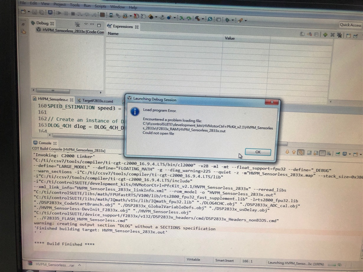
Green Deng:
回复 user5913644:
我跟你改成一样的,但是可以烧写啊。
你的target configuration设置的正确吗?
或者你可以找个简单的例程试一下:C:\ti\controlSUITE\device_support\f2833x\v142\DSP2833x_examples_ccsv5\gpio_toggle
这个例程就是控制GPIO口的电平翻转,添加工程后只要add一个flash.cmd文件,并把ram.cmd文件exclude from build就可以debug烧写了。如果target configuration配置正确的话不需要做其他修改。
使用f28335
我們自己用了一個版子
僅拉出 部分接腳 和電源供給
目標是
斷電後程是能重跑
不會因為ccs的resume鍵停止 而停止
希望不用透過resume就可以自動執行
user5913644:
回复 Green Deng:
可以燒寫了 可是動作還是不對 斷電後 重新上電 無法跟原動作一下
85 84觸發 沒有作用 你的可以嗎
![TMS320F28379D: 导入例程出现故障Description Resource Path Location Type gmake: *** [gridconnectedinvlclfltr.obj] Error 1 gridConnectedInverterLCLFltr C/C++ Problem-TI中文支持网](https://www.ti2k.com/wp-content/uploads/ti2k/DeyiSupport_C2000_pastedimage1752114958744v1.jpg)


