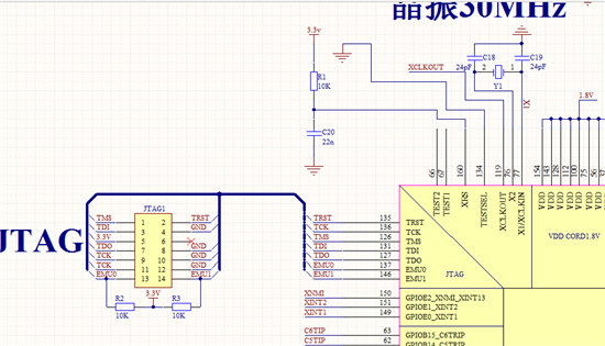
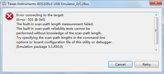
这个是原理图。连接的时候报错误
–
[Start: Texas Instruments XDS100v3 USB Emulator_0]
Execute the command:
%ccs_base%/common/uscif/dbgjtag -f %boarddatafile% -rv -o -F inform,logfile=yes -S pathlength -S integrity
[Result]
—–[Print the board config pathname(s)]————————————
C:\Users\ADMINI~1\AppData\Local\TEXASI~1\
CCS\ccs\0\0\BrdDat\testBoard.dat
—–[Print the reset-command software log-file]—————————–
This utility has selected a 100- or 510-class product.
This utility will load the adapter 'jioserdesusbv3.dll'.
The library build date was 'Mar 9 2014'.
The library build time was '22:27:48'.
The library package version is '5.1.450.0'.
The library component version is '35.34.40.0'.
The controller does not use a programmable FPGA.
The controller has a version number of '4' (0x00000004).
The controller has an insertion length of '0' (0x00000000).
This utility will attempt to reset the controller.
This utility has successfully reset the controller.
—–[Print the reset-command hardware log-file]—————————–
The scan-path will be reset by toggling the JTAG TRST signal.
The controller is the FTDI FT2232 with USB interface.
The link from controller to target is direct (without cable).
The software is configured for FTDI FT2232 features.
The controller cannot monitor the value on the EMU[0] pin.
The controller cannot monitor the value on the EMU[1] pin.
The controller cannot control the timing on output pins.
The controller cannot control the timing on input pins.
The scan-path link-delay has been set to exactly '0' (0x0000).
An error occurred while hard opening the controller.
—–[An error has occurred and this utility has aborted]——————–
This error is generated by TI's USCIF driver or utilities.
The value is '-501' (0xfffffe0b).
The title is 'SC_ERR_TEST_MEASURE'.
The explanation is:
The built-in scan-path length measurement failed.
The built-in scan-path reliability tests cannot be
performed without knowledge of the scan-path length.
Try specifying the scan-path lengths in the command-line
options or board configuration file of this utility or debugger.
[End: Texas Instruments XDS100v3 USB Emulator_0]
电源检测工作是正常的。可能是买到了带锁的芯片吗?因为我买的芯片是TMS320F2812PGFACE,我看了好多芯片上面写得都是TMS320F2812PGFACG
开发环境是CCS6.0、控制器是2812。
Seven Han:
请问您芯片从哪里买到的呢?
可参加下:http://www.deyisupport.com/question_answer/microcontrollers/c2000/f/56/t/141429.aspx
这个是原理图。连接的时候报错误
–
[Start: Texas Instruments XDS100v3 USB Emulator_0]
Execute the command:
%ccs_base%/common/uscif/dbgjtag -f %boarddatafile% -rv -o -F inform,logfile=yes -S pathlength -S integrity
[Result]
—–[Print the board config pathname(s)]————————————
C:\Users\ADMINI~1\AppData\Local\TEXASI~1\
CCS\ccs\0\0\BrdDat\testBoard.dat
—–[Print the reset-command software log-file]—————————–
This utility has selected a 100- or 510-class product.
This utility will load the adapter 'jioserdesusbv3.dll'.
The library build date was 'Mar 9 2014'.
The library build time was '22:27:48'.
The library package version is '5.1.450.0'.
The library component version is '35.34.40.0'.
The controller does not use a programmable FPGA.
The controller has a version number of '4' (0x00000004).
The controller has an insertion length of '0' (0x00000000).
This utility will attempt to reset the controller.
This utility has successfully reset the controller.
—–[Print the reset-command hardware log-file]—————————–
The scan-path will be reset by toggling the JTAG TRST signal.
The controller is the FTDI FT2232 with USB interface.
The link from controller to target is direct (without cable).
The software is configured for FTDI FT2232 features.
The controller cannot monitor the value on the EMU[0] pin.
The controller cannot monitor the value on the EMU[1] pin.
The controller cannot control the timing on output pins.
The controller cannot control the timing on input pins.
The scan-path link-delay has been set to exactly '0' (0x0000).
An error occurred while hard opening the controller.
—–[An error has occurred and this utility has aborted]——————–
This error is generated by TI's USCIF driver or utilities.
The value is '-501' (0xfffffe0b).
The title is 'SC_ERR_TEST_MEASURE'.
The explanation is:
The built-in scan-path length measurement failed.
The built-in scan-path reliability tests cannot be
performed without knowledge of the scan-path length.
Try specifying the scan-path lengths in the command-line
options or board configuration file of this utility or debugger.
[End: Texas Instruments XDS100v3 USB Emulator_0]
电源检测工作是正常的。可能是买到了带锁的芯片吗?因为我买的芯片是TMS320F2812PGFACE,我看了好多芯片上面写得都是TMS320F2812PGFACG
开发环境是CCS6.0、控制器是2812。
Eric Ma:
电源检测工作是正常的。可能是买到了带锁的芯片吗?因为我买的芯片是TMS320F2812PGFACE,我看了好多芯片上面写得都是TMS320F2812PGFACG
ERIC:
如果是上锁的话,那可以通过将RESET引脚下拉到地,然后连接仿真器,如果成功,则是上锁。
这个是原理图。连接的时候报错误
–
[Start: Texas Instruments XDS100v3 USB Emulator_0]
Execute the command:
%ccs_base%/common/uscif/dbgjtag -f %boarddatafile% -rv -o -F inform,logfile=yes -S pathlength -S integrity
[Result]
—–[Print the board config pathname(s)]————————————
C:\Users\ADMINI~1\AppData\Local\TEXASI~1\
CCS\ccs\0\0\BrdDat\testBoard.dat
—–[Print the reset-command software log-file]—————————–
This utility has selected a 100- or 510-class product.
This utility will load the adapter 'jioserdesusbv3.dll'.
The library build date was 'Mar 9 2014'.
The library build time was '22:27:48'.
The library package version is '5.1.450.0'.
The library component version is '35.34.40.0'.
The controller does not use a programmable FPGA.
The controller has a version number of '4' (0x00000004).
The controller has an insertion length of '0' (0x00000000).
This utility will attempt to reset the controller.
This utility has successfully reset the controller.
—–[Print the reset-command hardware log-file]—————————–
The scan-path will be reset by toggling the JTAG TRST signal.
The controller is the FTDI FT2232 with USB interface.
The link from controller to target is direct (without cable).
The software is configured for FTDI FT2232 features.
The controller cannot monitor the value on the EMU[0] pin.
The controller cannot monitor the value on the EMU[1] pin.
The controller cannot control the timing on output pins.
The controller cannot control the timing on input pins.
The scan-path link-delay has been set to exactly '0' (0x0000).
An error occurred while hard opening the controller.
—–[An error has occurred and this utility has aborted]——————–
This error is generated by TI's USCIF driver or utilities.
The value is '-501' (0xfffffe0b).
The title is 'SC_ERR_TEST_MEASURE'.
The explanation is:
The built-in scan-path length measurement failed.
The built-in scan-path reliability tests cannot be
performed without knowledge of the scan-path length.
Try specifying the scan-path lengths in the command-line
options or board configuration file of this utility or debugger.
[End: Texas Instruments XDS100v3 USB Emulator_0]
电源检测工作是正常的。可能是买到了带锁的芯片吗?因为我买的芯片是TMS320F2812PGFACE,我看了好多芯片上面写得都是TMS320F2812PGFACG
开发环境是CCS6.0、控制器是2812。
bo ruan:
回复 Eric Ma:
我把REST接地了还是连接不上。焊接确实没问题我把原理图贴出来您看看硬件上有没有问题!谢谢
刚刚用是示波器测了下CLKOUT脚时钟有输出。
我电路中MP\MC 引脚直接接地应该没什么影响吧。

这个是原理图。连接的时候报错误
–
[Start: Texas Instruments XDS100v3 USB Emulator_0]
Execute the command:
%ccs_base%/common/uscif/dbgjtag -f %boarddatafile% -rv -o -F inform,logfile=yes -S pathlength -S integrity
[Result]
—–[Print the board config pathname(s)]————————————
C:\Users\ADMINI~1\AppData\Local\TEXASI~1\
CCS\ccs\0\0\BrdDat\testBoard.dat
—–[Print the reset-command software log-file]—————————–
This utility has selected a 100- or 510-class product.
This utility will load the adapter 'jioserdesusbv3.dll'.
The library build date was 'Mar 9 2014'.
The library build time was '22:27:48'.
The library package version is '5.1.450.0'.
The library component version is '35.34.40.0'.
The controller does not use a programmable FPGA.
The controller has a version number of '4' (0x00000004).
The controller has an insertion length of '0' (0x00000000).
This utility will attempt to reset the controller.
This utility has successfully reset the controller.
—–[Print the reset-command hardware log-file]—————————–
The scan-path will be reset by toggling the JTAG TRST signal.
The controller is the FTDI FT2232 with USB interface.
The link from controller to target is direct (without cable).
The software is configured for FTDI FT2232 features.
The controller cannot monitor the value on the EMU[0] pin.
The controller cannot monitor the value on the EMU[1] pin.
The controller cannot control the timing on output pins.
The controller cannot control the timing on input pins.
The scan-path link-delay has been set to exactly '0' (0x0000).
An error occurred while hard opening the controller.
—–[An error has occurred and this utility has aborted]——————–
This error is generated by TI's USCIF driver or utilities.
The value is '-501' (0xfffffe0b).
The title is 'SC_ERR_TEST_MEASURE'.
The explanation is:
The built-in scan-path length measurement failed.
The built-in scan-path reliability tests cannot be
performed without knowledge of the scan-path length.
Try specifying the scan-path lengths in the command-line
options or board configuration file of this utility or debugger.
[End: Texas Instruments XDS100v3 USB Emulator_0]
电源检测工作是正常的。可能是买到了带锁的芯片吗?因为我买的芯片是TMS320F2812PGFACE,我看了好多芯片上面写得都是TMS320F2812PGFACG
开发环境是CCS6.0、控制器是2812。
bo ruan:
回复 Seven Han:
您好! 我的复位电路是10K+10UF。请问这个硬件设计手册里面对时序有要求,不知道这个对JTAG的连接有影响吗?

