最近刚做了一块28035的板子,焊完之后测试连不上仿真器,仿真器是南京研旭的,可以确认没有问题,在28335的板子上可以正常使用的。
连28035的时候测试结果如下:
[Start: Texas Instruments XDS100v3 USB Debug Probe_0]
Execute the command:
%ccs_base%/common/uscif/dbgjtag -f %boarddatafile% -rv -o -F inform,logfile=yes -S pathlength -S integrity
[Result]
—–[Print the board config pathname(s)]————————————
C:\Users\JSH\AppData\Local\TEXASI~1\CCS\
ti\1\0\BrdDat\testBoard.dat
—–[Print the reset-command software log-file]—————————–
This utility has selected a 100- or 510-class product.
This utility will load the adapter 'jioserdesusbv3.dll'.
The library build date was 'May 23 2017'.
The library build time was '19:37:36'.
The library package version is '6.0.628.3'.
The library component version is '35.35.0.0'.
The controller does not use a programmable FPGA.
The controller has a version number of '4' (0x00000004).
The controller has an insertion length of '0' (0x00000000).
This utility will attempt to reset the controller.
This utility has successfully reset the controller.
—–[Print the reset-command hardware log-file]—————————–
The scan-path will be reset by toggling the JTAG TRST signal.
The controller is the FTDI FT2232 with USB interface.
The link from controller to target is direct (without cable).
The software is configured for FTDI FT2232 features.
The controller cannot monitor the value on the EMU[0] pin.
The controller cannot monitor the value on the EMU[1] pin.
The controller cannot control the timing on output pins.
The controller cannot control the timing on input pins.
The scan-path link-delay has been set to exactly '0' (0x0000).
An error occurred while hard opening the controller.
—–[An error has occurred and this utility has aborted]——————–
This error is generated by TI's USCIF driver or utilities.
The value is '-233' (0xffffff17).
The title is 'SC_ERR_PATH_BROKEN'.
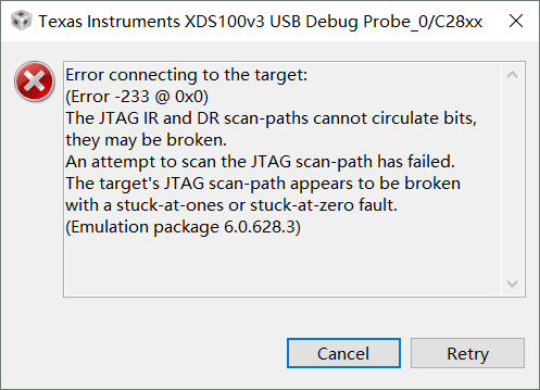
The explanation is:
The JTAG IR and DR scan-paths cannot circulate bits, they may be broken.
An attempt to scan the JTAG scan-path has failed.
The target's JTAG scan-path appears to be broken
with a stuck-at-ones or stuck-at-zero fault.
[End: Texas Instruments XDS100v3 USB Debug Probe_0]
已经在网上查了好多资料,可以排除电源问题,仿真器接口顺序问题,仿真器接口接触不良问题。现在的板子用的是外部晶振,12MHz的。我看输入范围是5-20MHz,应该没有问题吧,匹配电容和在别的ARM板上用的是一样的。后来发现28035可以使用内部时钟,于是安装手册里的说明,把X1接地,X2悬空,连接测试结果跟上面一样。直接点debug按钮弹出的窗口如下
 还有那些地方需要注意和测试的请各位前辈指点一下。
Seven Han:
您好,用示波器测XCLKOUT引脚,看28035是否处于正常工作状态;若XCLKOUT输出不正常的话,检查电源以及XRSN;注意JTAG与28035接触良好。
最近刚做了一块28035的板子,焊完之后测试连不上仿真器,仿真器是南京研旭的,可以确认没有问题,在28335的板子上可以正常使用的。
连28035的时候测试结果如下:
[Start: Texas Instruments XDS100v3 USB Debug Probe_0]
Execute the command:
%ccs_base%/common/uscif/dbgjtag -f %boarddatafile% -rv -o -F inform,logfile=yes -S pathlength -S integrity
[Result]
—–[Print the board config pathname(s)]————————————
C:\Users\JSH\AppData\Local\TEXASI~1\CCS\
ti\1\0\BrdDat\testBoard.dat
—–[Print the reset-command software log-file]—————————–
This utility has selected a 100- or 510-class product.
This utility will load the adapter 'jioserdesusbv3.dll'.
The library build date was 'May 23 2017'.
The library build time was '19:37:36'.
The library package version is '6.0.628.3'.
The library component version is '35.35.0.0'.
The controller does not use a programmable FPGA.
The controller has a version number of '4' (0x00000004).
The controller has an insertion length of '0' (0x00000000).
This utility will attempt to reset the controller.
This utility has successfully reset the controller.
—–[Print the reset-command hardware log-file]—————————–
The scan-path will be reset by toggling the JTAG TRST signal.
The controller is the FTDI FT2232 with USB interface.
The link from controller to target is direct (without cable).
The software is configured for FTDI FT2232 features.
The controller cannot monitor the value on the EMU[0] pin.
The controller cannot monitor the value on the EMU[1] pin.
The controller cannot control the timing on output pins.
The controller cannot control the timing on input pins.
The scan-path link-delay has been set to exactly '0' (0x0000).
An error occurred while hard opening the controller.
—–[An error has occurred and this utility has aborted]——————–
This error is generated by TI's USCIF driver or utilities.
The value is '-233' (0xffffff17).
The title is 'SC_ERR_PATH_BROKEN'.
The explanation is:
The JTAG IR and DR scan-paths cannot circulate bits, they may be broken.
An attempt to scan the JTAG scan-path has failed.
The target's JTAG scan-path appears to be broken
with a stuck-at-ones or stuck-at-zero fault.
[End: Texas Instruments XDS100v3 USB Debug Probe_0]
已经在网上查了好多资料,可以排除电源问题,仿真器接口顺序问题,仿真器接口接触不良问题。现在的板子用的是外部晶振,12MHz的。我看输入范围是5-20MHz,应该没有问题吧,匹配电容和在别的ARM板上用的是一样的。后来发现28035可以使用内部时钟,于是安装手册里的说明,把X1接地,X2悬空,连接测试结果跟上面一样。直接点debug按钮弹出的窗口如下
还有那些地方需要注意和测试的请各位前辈指点一下。
user1988539:
回复 Seven Han:
谢谢。正在找示波器。只要芯片正常,不管是内部时钟还是外部晶体,都会在xclkout脚输出时钟信号是吧?
最近刚做了一块28035的板子,焊完之后测试连不上仿真器,仿真器是南京研旭的,可以确认没有问题,在28335的板子上可以正常使用的。
连28035的时候测试结果如下:
[Start: Texas Instruments XDS100v3 USB Debug Probe_0]
Execute the command:
%ccs_base%/common/uscif/dbgjtag -f %boarddatafile% -rv -o -F inform,logfile=yes -S pathlength -S integrity
[Result]
—–[Print the board config pathname(s)]————————————
C:\Users\JSH\AppData\Local\TEXASI~1\CCS\
ti\1\0\BrdDat\testBoard.dat
—–[Print the reset-command software log-file]—————————–
This utility has selected a 100- or 510-class product.
This utility will load the adapter 'jioserdesusbv3.dll'.
The library build date was 'May 23 2017'.
The library build time was '19:37:36'.
The library package version is '6.0.628.3'.
The library component version is '35.35.0.0'.
The controller does not use a programmable FPGA.
The controller has a version number of '4' (0x00000004).
The controller has an insertion length of '0' (0x00000000).
This utility will attempt to reset the controller.
This utility has successfully reset the controller.
—–[Print the reset-command hardware log-file]—————————–
The scan-path will be reset by toggling the JTAG TRST signal.
The controller is the FTDI FT2232 with USB interface.
The link from controller to target is direct (without cable).
The software is configured for FTDI FT2232 features.
The controller cannot monitor the value on the EMU[0] pin.
The controller cannot monitor the value on the EMU[1] pin.
The controller cannot control the timing on output pins.
The controller cannot control the timing on input pins.
The scan-path link-delay has been set to exactly '0' (0x0000).
An error occurred while hard opening the controller.
—–[An error has occurred and this utility has aborted]——————–
This error is generated by TI's USCIF driver or utilities.
The value is '-233' (0xffffff17).
The title is 'SC_ERR_PATH_BROKEN'.
The explanation is:
The JTAG IR and DR scan-paths cannot circulate bits, they may be broken.
An attempt to scan the JTAG scan-path has failed.
The target's JTAG scan-path appears to be broken
with a stuck-at-ones or stuck-at-zero fault.
[End: Texas Instruments XDS100v3 USB Debug Probe_0]
已经在网上查了好多资料,可以排除电源问题,仿真器接口顺序问题,仿真器接口接触不良问题。现在的板子用的是外部晶振,12MHz的。我看输入范围是5-20MHz,应该没有问题吧,匹配电容和在别的ARM板上用的是一样的。后来发现28035可以使用内部时钟,于是安装手册里的说明,把X1接地,X2悬空,连接测试结果跟上面一样。直接点debug按钮弹出的窗口如下
还有那些地方需要注意和测试的请各位前辈指点一下。
Seven Han:
回复 user1988539:
是的,这样的问题若能排除仿真器原因后,需主要检查硬件,一般先看下板子电源,时钟输出是否稳定,焊接等问题。
最近刚做了一块28035的板子,焊完之后测试连不上仿真器,仿真器是南京研旭的,可以确认没有问题,在28335的板子上可以正常使用的。
连28035的时候测试结果如下:
[Start: Texas Instruments XDS100v3 USB Debug Probe_0]
Execute the command:
%ccs_base%/common/uscif/dbgjtag -f %boarddatafile% -rv -o -F inform,logfile=yes -S pathlength -S integrity
[Result]
—–[Print the board config pathname(s)]————————————
C:\Users\JSH\AppData\Local\TEXASI~1\CCS\
ti\1\0\BrdDat\testBoard.dat
—–[Print the reset-command software log-file]—————————–
This utility has selected a 100- or 510-class product.
This utility will load the adapter 'jioserdesusbv3.dll'.
The library build date was 'May 23 2017'.
The library build time was '19:37:36'.
The library package version is '6.0.628.3'.
The library component version is '35.35.0.0'.
The controller does not use a programmable FPGA.
The controller has a version number of '4' (0x00000004).
The controller has an insertion length of '0' (0x00000000).
This utility will attempt to reset the controller.
This utility has successfully reset the controller.
—–[Print the reset-command hardware log-file]—————————–
The scan-path will be reset by toggling the JTAG TRST signal.
The controller is the FTDI FT2232 with USB interface.
The link from controller to target is direct (without cable).
The software is configured for FTDI FT2232 features.
The controller cannot monitor the value on the EMU[0] pin.
The controller cannot monitor the value on the EMU[1] pin.
The controller cannot control the timing on output pins.
The controller cannot control the timing on input pins.
The scan-path link-delay has been set to exactly '0' (0x0000).
An error occurred while hard opening the controller.
—–[An error has occurred and this utility has aborted]——————–
This error is generated by TI's USCIF driver or utilities.
The value is '-233' (0xffffff17).
The title is 'SC_ERR_PATH_BROKEN'.
The explanation is:
The JTAG IR and DR scan-paths cannot circulate bits, they may be broken.
An attempt to scan the JTAG scan-path has failed.
The target's JTAG scan-path appears to be broken
with a stuck-at-ones or stuck-at-zero fault.
[End: Texas Instruments XDS100v3 USB Debug Probe_0]
已经在网上查了好多资料,可以排除电源问题,仿真器接口顺序问题,仿真器接口接触不良问题。现在的板子用的是外部晶振,12MHz的。我看输入范围是5-20MHz,应该没有问题吧,匹配电容和在别的ARM板上用的是一样的。后来发现28035可以使用内部时钟,于是安装手册里的说明,把X1接地,X2悬空,连接测试结果跟上面一样。直接点debug按钮弹出的窗口如下
还有那些地方需要注意和测试的请各位前辈指点一下。
user1988539:
回复 Eric Ma:
问题找到了,各个地方的设计与参考设计均一致,但是做封装的人把56、57脚的序号弄错 了,导致TCK信号没有到仿真器的针脚上,开始量的时候没有仔细量。没有发现
谢谢


