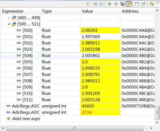
程序用了一路输入A0,然后给DSP28335 ADCINA0引脚上加上一个正弦波 寄存器显示依然是那个常量大概2730左右换算成电压就是2.0V。请问是为什么?
程序如下:
void main(void)
{
Uint16 i;
Uint16 array_index;
InitSysCtrl();
asm(" RPT #8 || NOP");
DINT;
InitGpio();
DINT;
InitPieCtrl();
DINT;
InitFlash();
IER = 0x0000;
IFR = 0x0000;
InitPieVectTable();
asm(" RPT #8 || NOP");
InitAdc(); // For this example, init the ADC
EALLOW;
SysCtrlRegs.HISPCP.all = ADC_MODCLK; // HSPCLK = SYSCLKOUT/ADC_MODCLK
EDIS;
// Secific ADC setup for this example:
AdcRegs.ADCTRL1.bit.ACQ_PS = ADC_SHCLK; // Sequential mode: Sample rate = 1/[(2+ACQ_PS)*ADC clock in ns]
// = 1/(3*40ns) =8.3MHz (for 150 MHz SYSCLKOUT)
// = 1/(3*80ns) =4.17MHz (for 100 MHz SYSCLKOUT)
// If Simultaneous mode enabled: Sample rate = 1/[(3+ACQ_PS)*ADC clock in ns]
AdcRegs.ADCTRL3.bit.ADCCLKPS = ADC_CKPS;
AdcRegs.ADCTRL1.bit.SEQ_CASC = 1; // 1 Cascaded mode
AdcRegs.ADCTRL3.bit.SMODE_SEL=0;
// AdcRegs.ADCCHSELSEQ1.bit.CONV00 = 0x0;
// AdcRegs.ADCCHSELSEQ1.bit.CONV01 = 0x0;
// AdcRegs.ADCCHSELSEQ1.bit.CONV02 = 0x0;
// AdcRegs.ADCCHSELSEQ1.bit.CONV03 = 0x0;
// AdcRegs.ADCCHSELSEQ2.bit.CONV04 = 0x0;
// AdcRegs.ADCCHSELSEQ2.bit.CONV05 = 0x0;
// AdcRegs.ADCCHSELSEQ2.bit.CONV06 = 0x0;
// AdcRegs.ADCCHSELSEQ2.bit.CONV07 = 0x0;
// AdcRegs.ADCCHSELSEQ3.bit.CONV08 = 0x0;
// AdcRegs.ADCCHSELSEQ3.bit.CONV09 = 0x0;
// AdcRegs.ADCCHSELSEQ3.bit.CONV10 = 0x0;
// AdcRegs.ADCCHSELSEQ3.bit.CONV11 = 0x0;
// AdcRegs.ADCCHSELSEQ4.bit.CONV12 = 0x0;
// AdcRegs.ADCCHSELSEQ4.bit.CONV13 = 0x0;
// AdcRegs.ADCCHSELSEQ4.bit.CONV14 = 0x0;
// AdcRegs.ADCCHSELSEQ4.bit.CONV15 = 0x0;
AdcRegs.ADCMAXCONV.bit.MAX_CONV1 = 0x0;
AdcRegs.ADCCHSELSEQ1.all = 0x00;
AdcRegs.ADCTRL1.bit.CONT_RUN = 1; // Setup continuous run
AdcRegs.ADCTRL1.bit.SEQ_OVRD = 1; // Enable Sequencer override feature
AdcRegs.ADCMAXCONV.all=0x0000; //convert and store in 8 results registers
DINT;
// Clear SampleTable
for (i=0; i<BUF_SIZE; i++)
{
SampleTable0[i] = 0;
// SampleTable1[i] = 0;
}
// Start SEQ1
AdcRegs.ADCTRL2.all = 0x2000;
while(1)
{
configtestledOFF();
DELAY_US(50000);
array_index = 0;
for (i=0; i<BUF_SIZE; i++)
{
while (AdcRegs.ADCST.bit.INT_SEQ1== 0){}
AdcRegs.ADCST.bit.INT_SEQ1_CLR = 1;
// AdcRegs.ADCTRL2.bit.RST_SEQ1 = 1;
SampleTable0[array_index++]= ( (AdcRegs.ADCRESULT0)>>4)*3.0/4095.0;
}
}
}
寄存器结果:
期待回复中
mangui zhang:
这种观测最好的方式是通过graph 然后打断点 通过不同的断点持续刷新就能够连续观测
如果一直没有变化 应该是配置的问题 并且刷新数据有变化 可能是读到的AD口悬空状态的值
程序用了一路输入A0,然后给DSP28335 ADCINA0引脚上加上一个正弦波 寄存器显示依然是那个常量大概2730左右换算成电压就是2.0V。请问是为什么?
程序如下:
void main(void)
{
Uint16 i;
Uint16 array_index;
InitSysCtrl();
asm(" RPT #8 || NOP");
DINT;
InitGpio();
DINT;
InitPieCtrl();
DINT;
InitFlash();
IER = 0x0000;
IFR = 0x0000;
InitPieVectTable();
asm(" RPT #8 || NOP");
InitAdc(); // For this example, init the ADC
EALLOW;
SysCtrlRegs.HISPCP.all = ADC_MODCLK; // HSPCLK = SYSCLKOUT/ADC_MODCLK
EDIS;
// Secific ADC setup for this example:
AdcRegs.ADCTRL1.bit.ACQ_PS = ADC_SHCLK; // Sequential mode: Sample rate = 1/[(2+ACQ_PS)*ADC clock in ns]
// = 1/(3*40ns) =8.3MHz (for 150 MHz SYSCLKOUT)
// = 1/(3*80ns) =4.17MHz (for 100 MHz SYSCLKOUT)
// If Simultaneous mode enabled: Sample rate = 1/[(3+ACQ_PS)*ADC clock in ns]
AdcRegs.ADCTRL3.bit.ADCCLKPS = ADC_CKPS;
AdcRegs.ADCTRL1.bit.SEQ_CASC = 1; // 1 Cascaded mode
AdcRegs.ADCTRL3.bit.SMODE_SEL=0;
// AdcRegs.ADCCHSELSEQ1.bit.CONV00 = 0x0;
// AdcRegs.ADCCHSELSEQ1.bit.CONV01 = 0x0;
// AdcRegs.ADCCHSELSEQ1.bit.CONV02 = 0x0;
// AdcRegs.ADCCHSELSEQ1.bit.CONV03 = 0x0;
// AdcRegs.ADCCHSELSEQ2.bit.CONV04 = 0x0;
// AdcRegs.ADCCHSELSEQ2.bit.CONV05 = 0x0;
// AdcRegs.ADCCHSELSEQ2.bit.CONV06 = 0x0;
// AdcRegs.ADCCHSELSEQ2.bit.CONV07 = 0x0;
// AdcRegs.ADCCHSELSEQ3.bit.CONV08 = 0x0;
// AdcRegs.ADCCHSELSEQ3.bit.CONV09 = 0x0;
// AdcRegs.ADCCHSELSEQ3.bit.CONV10 = 0x0;
// AdcRegs.ADCCHSELSEQ3.bit.CONV11 = 0x0;
// AdcRegs.ADCCHSELSEQ4.bit.CONV12 = 0x0;
// AdcRegs.ADCCHSELSEQ4.bit.CONV13 = 0x0;
// AdcRegs.ADCCHSELSEQ4.bit.CONV14 = 0x0;
// AdcRegs.ADCCHSELSEQ4.bit.CONV15 = 0x0;
AdcRegs.ADCMAXCONV.bit.MAX_CONV1 = 0x0;
AdcRegs.ADCCHSELSEQ1.all = 0x00;
AdcRegs.ADCTRL1.bit.CONT_RUN = 1; // Setup continuous run
AdcRegs.ADCTRL1.bit.SEQ_OVRD = 1; // Enable Sequencer override feature
AdcRegs.ADCMAXCONV.all=0x0000; //convert and store in 8 results registers
DINT;
// Clear SampleTable
for (i=0; i<BUF_SIZE; i++)
{
SampleTable0[i] = 0;
// SampleTable1[i] = 0;
}
// Start SEQ1
AdcRegs.ADCTRL2.all = 0x2000;
while(1)
{
configtestledOFF();
DELAY_US(50000);
array_index = 0;
for (i=0; i<BUF_SIZE; i++)
{
while (AdcRegs.ADCST.bit.INT_SEQ1== 0){}
AdcRegs.ADCST.bit.INT_SEQ1_CLR = 1;
// AdcRegs.ADCTRL2.bit.RST_SEQ1 = 1;
SampleTable0[array_index++]= ( (AdcRegs.ADCRESULT0)>>4)*3.0/4095.0;
}
}
}
寄存器结果:
期待回复中
yq k:
回复 mangui zhang:
mangui zhang
这种观测最好的方式是通过graph 然后打断点 通过不同的断点持续刷新就能够连续观测
如果一直没有变化 应该是配置的问题 并且刷新数据有变化 可能是读到的AD口悬空状态的值
程序用了一路输入A0,然后给DSP28335 ADCINA0引脚上加上一个正弦波 寄存器显示依然是那个常量大概2730左右换算成电压就是2.0V。请问是为什么?
程序如下:
void main(void)
{
Uint16 i;
Uint16 array_index;
InitSysCtrl();
asm(" RPT #8 || NOP");
DINT;
InitGpio();
DINT;
InitPieCtrl();
DINT;
InitFlash();
IER = 0x0000;
IFR = 0x0000;
InitPieVectTable();
asm(" RPT #8 || NOP");
InitAdc(); // For this example, init the ADC
EALLOW;
SysCtrlRegs.HISPCP.all = ADC_MODCLK; // HSPCLK = SYSCLKOUT/ADC_MODCLK
EDIS;
// Secific ADC setup for this example:
AdcRegs.ADCTRL1.bit.ACQ_PS = ADC_SHCLK; // Sequential mode: Sample rate = 1/[(2+ACQ_PS)*ADC clock in ns]
// = 1/(3*40ns) =8.3MHz (for 150 MHz SYSCLKOUT)
// = 1/(3*80ns) =4.17MHz (for 100 MHz SYSCLKOUT)
// If Simultaneous mode enabled: Sample rate = 1/[(3+ACQ_PS)*ADC clock in ns]
AdcRegs.ADCTRL3.bit.ADCCLKPS = ADC_CKPS;
AdcRegs.ADCTRL1.bit.SEQ_CASC = 1; // 1 Cascaded mode
AdcRegs.ADCTRL3.bit.SMODE_SEL=0;
// AdcRegs.ADCCHSELSEQ1.bit.CONV00 = 0x0;
// AdcRegs.ADCCHSELSEQ1.bit.CONV01 = 0x0;
// AdcRegs.ADCCHSELSEQ1.bit.CONV02 = 0x0;
// AdcRegs.ADCCHSELSEQ1.bit.CONV03 = 0x0;
// AdcRegs.ADCCHSELSEQ2.bit.CONV04 = 0x0;
// AdcRegs.ADCCHSELSEQ2.bit.CONV05 = 0x0;
// AdcRegs.ADCCHSELSEQ2.bit.CONV06 = 0x0;
// AdcRegs.ADCCHSELSEQ2.bit.CONV07 = 0x0;
// AdcRegs.ADCCHSELSEQ3.bit.CONV08 = 0x0;
// AdcRegs.ADCCHSELSEQ3.bit.CONV09 = 0x0;
// AdcRegs.ADCCHSELSEQ3.bit.CONV10 = 0x0;
// AdcRegs.ADCCHSELSEQ3.bit.CONV11 = 0x0;
// AdcRegs.ADCCHSELSEQ4.bit.CONV12 = 0x0;
// AdcRegs.ADCCHSELSEQ4.bit.CONV13 = 0x0;
// AdcRegs.ADCCHSELSEQ4.bit.CONV14 = 0x0;
// AdcRegs.ADCCHSELSEQ4.bit.CONV15 = 0x0;
AdcRegs.ADCMAXCONV.bit.MAX_CONV1 = 0x0;
AdcRegs.ADCCHSELSEQ1.all = 0x00;
AdcRegs.ADCTRL1.bit.CONT_RUN = 1; // Setup continuous run
AdcRegs.ADCTRL1.bit.SEQ_OVRD = 1; // Enable Sequencer override feature
AdcRegs.ADCMAXCONV.all=0x0000; //convert and store in 8 results registers
DINT;
// Clear SampleTable
for (i=0; i<BUF_SIZE; i++)
{
SampleTable0[i] = 0;
// SampleTable1[i] = 0;
}
// Start SEQ1
AdcRegs.ADCTRL2.all = 0x2000;
while(1)
{
configtestledOFF();
DELAY_US(50000);
array_index = 0;
for (i=0; i<BUF_SIZE; i++)
{
while (AdcRegs.ADCST.bit.INT_SEQ1== 0){}
AdcRegs.ADCST.bit.INT_SEQ1_CLR = 1;
// AdcRegs.ADCTRL2.bit.RST_SEQ1 = 1;
SampleTable0[array_index++]= ( (AdcRegs.ADCRESULT0)>>4)*3.0/4095.0;
}
}
}
寄存器结果:
期待回复中
Seven Han:
尝试测一下ADC引脚上的波形看看有没有问题,没有问题的话可能就是程序的问题了。


